Schwinn Panther build

Little update, been busy with other stuff lately. My new seat came it's the one on the right. Block work being done pockets for oversized springs and 5 hp lifters, valve grind and head cut.
8cdc1b86a0482510724caa2baf12755e_zpscc59af8c.jpg

f4a09fe4f6314dae7971cfd9d46a482c_zpsd8a55fa0.jpg

9411046b7e097361cfa35407003ab2c4_zps2557737a.jpg

ab20cbea1a333bd0455fb1ef2b92efbe_zps349b65d1.jpg

ebe2e7d3cfe734d32c262c4b5a4d603c_zps7ac20d35.jpg
 
Hot cam has such a high lift that a bit of the counter balance on crank will have to be ground. Re -doing jackshaft mount and using a pair of flange mount bearing blocks mounted to a plate welded at 90 degrees from post tube.
e65cfa2fe3ef0af4f9ef58e899fb9b98_zps3eebe31d.jpg
 
Wow Awesome work Chain!

What do you think about using those bar mounts to make an engine mount out of? I was thinking about doing that to mine since I can no longer use the stock mount and plate. Either that or I have to get someone to weld it up and make a new plate.
 
Not sure how they would work in the position needed they would be angled up. This is the method that worked for my first panther, simple piece of angle iron ($8.00) cut and welded on.
 
Hmm I might have to do that, did you put a plate on top of the angle iron or was it wide enough to mount the engine on by itself? Can you PM me the pic I dont want to derail your thread lol.

Edit you nija'd that pic in as I was typing lol
 
Hi, it's me, Axel from germany

looks like you've got an original Mesinger seat at home, could you give me some numbers i.e. length and width? I am planning to build a set of Mesinger clones for my bikes.

Thanks
 
Those brackets for the jackshaft and the quality type bearings look great! The engine nicely degreased and on a perfectly clean baking tray wow too.

Yep, the angle bracket way is good and I added a few more attachment points as I intent hard use.

The angle brackets for a engine platform I did as an earlier build I did where my dad helped and braised the platform to the tubes. There was a slot for the bolts not holes. That allowed moving engine forward and aft to adjust tension on a belt drive without any clutch.

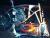
The picture shown attached, yet at night and not too clear is the current one welded that I did. I added more to the bottom of the platform to add strength. The parts attached to the top and lower bars was to help avoid all the stress cracking the bottom tube by spreading out the weight.

I do the no pedal dirt bike riding and it is hard on the frame. Gotta be over 40 years ago had the frame crack right there. Numb skull as a teenager, I continued to ride it with about and inch gap in the tubing till my dad had time to get it to the shop. Now I have my own MIG so no more of that.

MT
 

Attachments

  • IMG04218-20110709-2342.JPG
    IMG04218-20110709-2342.JPG
    470.6 KB · Views: 230
Project update, managed to mount one tire by hand...popped the inner tube on the front while trying so I need to get a set of tire spoons and a new tube. I was able to grind the front counterbalance for the cam lobe to clear and now I am running into a similar situation with the rear lobe hitting the rod where it widens at the bottom. The motor is definitely not engineered for such a high lift cam. I'm going to grind a bit off the width of the rear lobe for clearance. Have quite a bit to fit and do this week, the bike goes off to the welders next week. Sorry no pics will post some later.
 
Back
Top