58s Schwinn Wasp Build (My Dad's old bike)

Great project draco. Coming along nicely. Check out my thread on "cool tool for belt alignment". It's homemade and may be useful to you.

DSCN0085.jpg


DSCN0086.jpg
 
Thanks curt. The bar is 3/4'' X 1/8'' strap and the cones are aluminum round stock turned to a point on one end similar to the angle of most belts (but not that important because they find their way into the pulley and square up nicely), and are secured with screws.
Draco's motor generator is a really smart way to make a charging system. I used a Sturmey Archer Dynohub and had to regulate/rectify it with a cell phone charger from around 87v down to 7v or so to keep a small battery pack in the headlight housing charged. The motor looks like a simpler way to go. I like it.
 
THANKS these old eyes are getting tired when it comes to details. I think it would be handy for cars to.

Yes that is a good charging system. One can use just about any kind of brush type motor and spin it and it will put out juice,sowing machine,electric drill,you can also go to a Electrical machanical auto store and find all ginds of small chargers for lawn equipment that look like Draco's motor.

Also checkout this one on Ratrods http://www.ratrodbikes.com/forum/viewtopic.php?f=54&t=65777&st=0&sk=t&sd=a ,a neet kick start also...............Curt
 
Ok I got my gasket kit for the engine which has the exhaust gasket and intake gaskets. But what I have been wondering how to do, is loosen the head screws / bolts so I can replace them with more normal bolts.

They look like this when you look at them from the top...
Screw_head_-_cross.svg
 
They look like a Philips head screw but without the deep tapered center?
If so then they are like a double slotted flat blade screw?
If so the "slots" are rather shallow and if you use a standard flat blade screwdriver they like to "cam out" or slip out of the slots easily. You can use a flat bladed screwdriver with a hex drive bolster on the shank near the handle end. This allows you to put alot of downward pressure on the screwdriver to hold the bit into the shallow slot securely and still turn the screwdriver with the aid of a wrench slid onto the hex portion.
Like these: http://images.search.yahoo.com/sear...age&fr=yfp-t-701-s&va=hex+bolster+screwdriver

Or you can use a bit like this one:http://buy1.snapon.com/catalog/item...roup_ID=675560&store=snapon-store&dir=catalog

The bit is recessed inside a locating collar and helps prevent the bit from slipping out of the shallow slot. You have to be careful though, the collar needs to fit around the head of the screw rather snugly or it will not help prevent the slipping.
 
Last edited:
An impact driver would do the trick, HF has them for under $8 like this one, you line up the bit, smack it with a hammer and the driver twists from the impact. They work great.

Yea I bought one of those for another reason and will use it along with one of the bits from my Gun screw driver set. That way I will be using the right size flat blade bit to fit the head of the screw slot.
 
Braved the cold... well not totally cold, did have the propane heater going, but the garage has no insulation in it.

Added a brace to the Jack shaft mounting bracket so it can't rotate on me when the bike is under power.

attachment.php


attachment.php


attachment.php


attachment.php
 

Attachments

  • Jack shaft brace 1.jpg
    Jack shaft brace 1.jpg
    86.1 KB · Views: 1,139
  • Jack shaft brace 2.jpg
    Jack shaft brace 2.jpg
    80.3 KB · Views: 1,126
  • Jack shaft brace 3.jpg
    Jack shaft brace 3.jpg
    85.1 KB · Views: 534
  • Jack shaft brace 4.jpg
    Jack shaft brace 4.jpg
    111.2 KB · Views: 1,140
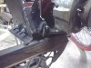
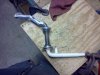
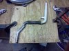
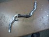
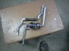
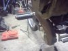
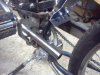
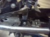
I was thinking I might also add another axis to gusset the angle brackets that I added to the bottom of my engine platform to hold the flat idler pulley I'm using on the 1st belt of my motor bike.

Dracothered, I suspect you have it worked out! When you get it hooked up running would like to see.

My thread:

http://motorbicycling.com/showthread.php?t=29678&page=12

Post #115 the latest pics using the regular vee-belt.

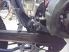
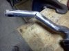
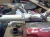
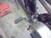
Msrfan's tool for lining up chain or belt, I did not make one of those, but got my 1st belt with the flat idler pulley lined up quite good I think. I did it by eye and noticed something I have yet to figure out why it happens.

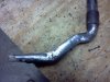
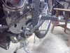
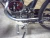
I had a question as to why you might explain as best I lined up the clutch pulley and the first pulley, when I rotate this belt in reverse while the engine is off it pulls slightly to the right.

(forgot to mention there is a slight crown to the flat idler, which if I had it over on the left side instead of center it did still pull to the right)


I would not have noticed it without having the flat idler pulley pushing on the back of the belt. Now it serves as a good reference point while I want it centered between the two walls on the flat idler.

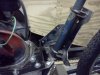
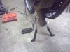
It moves only about an 1/8 of an inch to the right, but is repeatable. When going forward it is smack dead center between the walls of the flat idler pulley. It stays on track in either direction, and how much would I be walking the bike backward, so I guess it is not a problem.

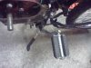
The amount it moves to the right with respect to center when moving forward, is that it is not going to go over the wall on the side of the flat idler pulley.

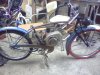
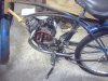
I would probably be removing the belt to the rear wheel pulley if I were to want to roll the bike either forward or backward a great deal of distance manually, as 40:1 ratio with these 3 snugged up belts just take a bit of force.

Any ideas why?

Thanks

MT
 
Last edited:
I found some information, but it is probably that misalignment by a small amount of the pulleys is the answer. The crown is supposed to actually keep it centered. How it does it may be far beyond what it is worth for me quite fully understand.

Here are the links:

http://www.durabelt.com/faq.php#FA11

"Note that crowns may not work on belts that frequently reverse direction, because it usually takes about three pulley revolutions before flat belts center themselves on crowns."

http://www.lhup.edu/~dsimanek/scenario/crowning.htm

http://www.lhup.edu/~dsimanek/scenario/crown-a.htm

MT
 
Finally got into the garage again to work on the bike. Worked on modifying a one peace crank so it will clear everything. Here is what I did, I cut a notch in the arm and bent it then I welded the notch back up.

attachment.php


attachment.php


attachment.php


attachment.php


attachment.php
 

Attachments

  • Modified Crank Arm 1.jpg
    Modified Crank Arm 1.jpg
    93.2 KB · Views: 753
  • Modified Crank Arm 2.jpg
    Modified Crank Arm 2.jpg
    70.5 KB · Views: 705
  • Modified Crank Arm 4.jpg
    Modified Crank Arm 4.jpg
    95.3 KB · Views: 703
  • Modified Crank Arm 5.jpg
    Modified Crank Arm 5.jpg
    90.3 KB · Views: 731
  • Modified Crank Arm 6.jpg
    Modified Crank Arm 6.jpg
    83.7 KB · Views: 691
Ok I did the other half of the crank... almost set the garage on fire while doing it though. Watch out for where your grinding sparks go or you could have this happen too.

attachment.php


attachment.php


Here is the crank assembly.

Notch cut for the bend.
attachment.php


Last weld still needs to be done, then it will be ready for test install.
attachment.php


Stock one next to modified one...
attachment.php
 

Attachments

  • fire 2.jpg
    fire 2.jpg
    89 KB · Views: 794
  • fire 1.jpg
    fire 1.jpg
    88 KB · Views: 813
  • Modified Crank Arm 7.jpg
    Modified Crank Arm 7.jpg
    78.4 KB · Views: 1,056
  • Modified Crank Arm 10.jpg
    Modified Crank Arm 10.jpg
    67.9 KB · Views: 1,033
  • Modified Crank Arm 11.jpg
    Modified Crank Arm 11.jpg
    83.3 KB · Views: 1,066
Nice work...one of the best I've seen! Poor T-Rex

Thanks MotoMagz

Yea poor T-Rex wasn't flame proof...

Here it is installed for a test fit.

attachment.php


attachment.php


attachment.php


attachment.php


attachment.php


Sat on the bike and did a test spin of the crank and it clears everything enough so now it can be pedaled
 

Attachments

  • Modified Crank Arm 12.jpg
    Modified Crank Arm 12.jpg
    95.4 KB · Views: 1,020
  • Modified Crank Arm 13.jpg
    Modified Crank Arm 13.jpg
    92.6 KB · Views: 648
  • Modified Crank Arm 14.jpg
    Modified Crank Arm 14.jpg
    91.8 KB · Views: 608
  • Modified Crank Arm 15.jpg
    Modified Crank Arm 15.jpg
    92.3 KB · Views: 1,005
  • Modified Crank Arm 16.jpg
    Modified Crank Arm 16.jpg
    80.1 KB · Views: 632

Attachments

  • Exhaust System 4.jpg
    Exhaust System 4.jpg
    94.9 KB · Views: 1,037
  • Exhaust System 5.jpg
    Exhaust System 5.jpg
    94.7 KB · Views: 1,055
  • Exhaust System 6.jpg
    Exhaust System 6.jpg
    97 KB · Views: 603
  • Exhaust System 7.jpg
    Exhaust System 7.jpg
    82 KB · Views: 637
Back
Top