silverbear
The Boy Who Never Grew Up
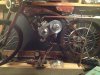
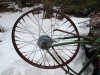
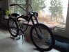
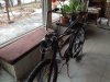
Time for an update and a little bit of show and tell. I stripped the bike down in order to paint the frame and wheels which are now done, even if there will be touching up later on.
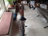
I've been house and pet sitting for my neighbors while they are on vacation to someplace warmer than northeastern Minnesota which includes just about everywhere. I set up a cot in their sun room overlooking a frozen version of Eaglesnest Lake 3, which has been a nice spot to re-assemble the bike and do some creative staring over coffee. I also polished up the gas tank and added a Whizzer logo piece salvaged from a plate from a Whizzer fork I bought some years ago and sold on a Panther build. Dug out the plate and removed the logo carefully which is now part of this build. Don't worry, Whizzerguys, I will clarify to anyone who asks that it is not a Whizzer, but is kindalikeawhizzer and a kind of tribute build. Is that Okay? If not, you may report me to the Whizzer police.
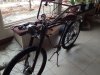
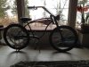
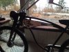
I like the brown, but did not like the gold seat with it as it was too bright. I wanted the copper to be what your eye goes to, not the seat. So I replaced it with a black version of the same great saddle which also has a lucky 7 seat post from a 1939 Elgin. It will require shimming to make it fit properly, but I have done that before with the Indian Hiawatha build and know how to make it secure. I like the position better and that it blends into the build. The other kind of bright stuff will be the cream accents and cream pin-stripping on the fenders once I get them repaired and painted.
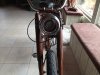
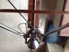
I finally got to see the handlebars on the frame and did some sitting in place to see how they feel. They come back too far and are also higher than is comfortable for me, so I will trim back the chromed steel a few inches and also shorten the copper extensions a few inches as well. I could make the whole handlebar set out of copper (which is what I'm doing with the Elgin Velocipede), but I think I'll go with this set being a kind of hybrid of metals and making it quite clear that they are hand made. Kind of a steam punk /industrial look sorta. Whatever, I like them and it's my bike, so there. I'm making up a set of foam grips covered in hand stitched black elk hide without fringe this time.
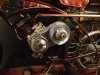
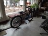
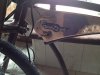
Due to the additional height of the fatty cyclops tires (26" X 2.4") the center kick stand needs to be altered so that both the rear drop stand and center stand legs all touch at the same time, making for a more secure support. I truly hate it for a bike to fall over. Not good. Altering the center stand legs will require cutting them with the tubing cutter and adding a junction connector on each leg. About a half hour job including re-soldering. The stand originally had aluminum legs which I amputated in order to make the legs out of copper and be of perfect length. The copper slips over aluminum "stubs" and each leg is held to the stub with a wee brass bolt and nut.
The rear drop stand was originally a kind of compromise since I wanted a stout welded steel one, but didn't know how to weld. So I made a "temporary" drop stand out of copper water pipe and fittings which I have found to be plenty strong enough to support a bike, simple to make and have now made three of them for different builds. I no longer care about welded steel ones since copper has been adequate and my use of it for jewel lights and all sorts of things has become a kind of signature saying "silverbear was here".
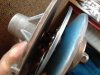
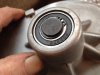
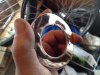
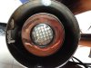
One more thing. Tinsmith indulged my juvenile wish for a copper doughnut to go inside the headlight I made. It looks nice, I think. Thank you, sir!
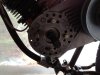
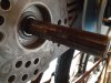
That's about it for now. I have some engine work to do and finishing up the engine mounts. Also fenders and little time consuming stuff that takes forever. The bike as it is will get stored away for the next month or two and attention now goes to the 1934 Elgin Velocipede sandwiched in between cutting and splitting firewood in preparation for next year's long, dark cold.
SB
I've been house and pet sitting for my neighbors while they are on vacation to someplace warmer than northeastern Minnesota which includes just about everywhere. I set up a cot in their sun room overlooking a frozen version of Eaglesnest Lake 3, which has been a nice spot to re-assemble the bike and do some creative staring over coffee. I also polished up the gas tank and added a Whizzer logo piece salvaged from a plate from a Whizzer fork I bought some years ago and sold on a Panther build. Dug out the plate and removed the logo carefully which is now part of this build. Don't worry, Whizzerguys, I will clarify to anyone who asks that it is not a Whizzer, but is kindalikeawhizzer and a kind of tribute build. Is that Okay? If not, you may report me to the Whizzer police.
I like the brown, but did not like the gold seat with it as it was too bright. I wanted the copper to be what your eye goes to, not the seat. So I replaced it with a black version of the same great saddle which also has a lucky 7 seat post from a 1939 Elgin. It will require shimming to make it fit properly, but I have done that before with the Indian Hiawatha build and know how to make it secure. I like the position better and that it blends into the build. The other kind of bright stuff will be the cream accents and cream pin-stripping on the fenders once I get them repaired and painted.
I finally got to see the handlebars on the frame and did some sitting in place to see how they feel. They come back too far and are also higher than is comfortable for me, so I will trim back the chromed steel a few inches and also shorten the copper extensions a few inches as well. I could make the whole handlebar set out of copper (which is what I'm doing with the Elgin Velocipede), but I think I'll go with this set being a kind of hybrid of metals and making it quite clear that they are hand made. Kind of a steam punk /industrial look sorta. Whatever, I like them and it's my bike, so there. I'm making up a set of foam grips covered in hand stitched black elk hide without fringe this time.
Due to the additional height of the fatty cyclops tires (26" X 2.4") the center kick stand needs to be altered so that both the rear drop stand and center stand legs all touch at the same time, making for a more secure support. I truly hate it for a bike to fall over. Not good. Altering the center stand legs will require cutting them with the tubing cutter and adding a junction connector on each leg. About a half hour job including re-soldering. The stand originally had aluminum legs which I amputated in order to make the legs out of copper and be of perfect length. The copper slips over aluminum "stubs" and each leg is held to the stub with a wee brass bolt and nut.
The rear drop stand was originally a kind of compromise since I wanted a stout welded steel one, but didn't know how to weld. So I made a "temporary" drop stand out of copper water pipe and fittings which I have found to be plenty strong enough to support a bike, simple to make and have now made three of them for different builds. I no longer care about welded steel ones since copper has been adequate and my use of it for jewel lights and all sorts of things has become a kind of signature saying "silverbear was here".
One more thing. Tinsmith indulged my juvenile wish for a copper doughnut to go inside the headlight I made. It looks nice, I think. Thank you, sir!
That's about it for now. I have some engine work to do and finishing up the engine mounts. Also fenders and little time consuming stuff that takes forever. The bike as it is will get stored away for the next month or two and attention now goes to the 1934 Elgin Velocipede sandwiched in between cutting and splitting firewood in preparation for next year's long, dark cold.
SB

")