Roll Your Own CDI

GoldenMotor.com

Are You Going to Roll Your Own CDI?


  • Total voters
    123

Ryoskate

New Member
Nov 30, 2015
58
0
0
Houston!
Here's some real good info on those aftermarket CDIs... (please read the entire thread).
http://motorbicycling.com/showthread.php?t=58455
I'm sorry but your method of experiment doesn't really say a lot.... Please, I'm appreciative of your effort and I'm not personally attacking you, but the timing you posted are nothing without context...

In order to make out anything useful from timing degrees, you'll have to record both RPM and timing at multiple points and plot it in a graph to see the actual CURVE, if any at all.

Does the timing retard after it reaches max advance? How steep is the curve? etc etc. You can't get any of that from just a single measurement.
 

WECSOG

Member
Nov 10, 2014
138
13
18
North Alabama, USA
I'm sorry but your method of experiment doesn't really say a lot.... Please, I'm appreciative of your effort and I'm not personally attacking you, but the timing you posted are nothing without context...

In order to make out anything useful from timing degrees, you'll have to record both RPM and timing at multiple points and plot it in a graph to see the actual CURVE, if any at all.

Does the timing retard after it reaches max advance? How steep is the curve? etc etc. You can't get any of that from just a single measurement.
He is comparing various CDI units at a given (3000) rpm, starting from the same fixed mechanical timing. While that doesn't plot a curve, it does give us useful information. None of these units actually advance the timing; they retard it at low rpm and the retard becomes less as rpm increases.
 

Venice Motor Bikes

Custom Builder / Dealer/Los Angeles
Mar 20, 2008
7,333
1,967
113
Los Angeles, CA.
I was simply trying to give this community some kind of info to help them figure out what part will work best for their needs.

If you've been around here for any length of time, you'd know that none of the makers of these CDIs ever provided a single bit of of test info about what their parts actually do.
(All they ever did was talk trash & say theirs works the best).
 

LS614

Active Member
Dec 22, 2009
1,236
3
38
CT and MA
Made my own

Hi guys,
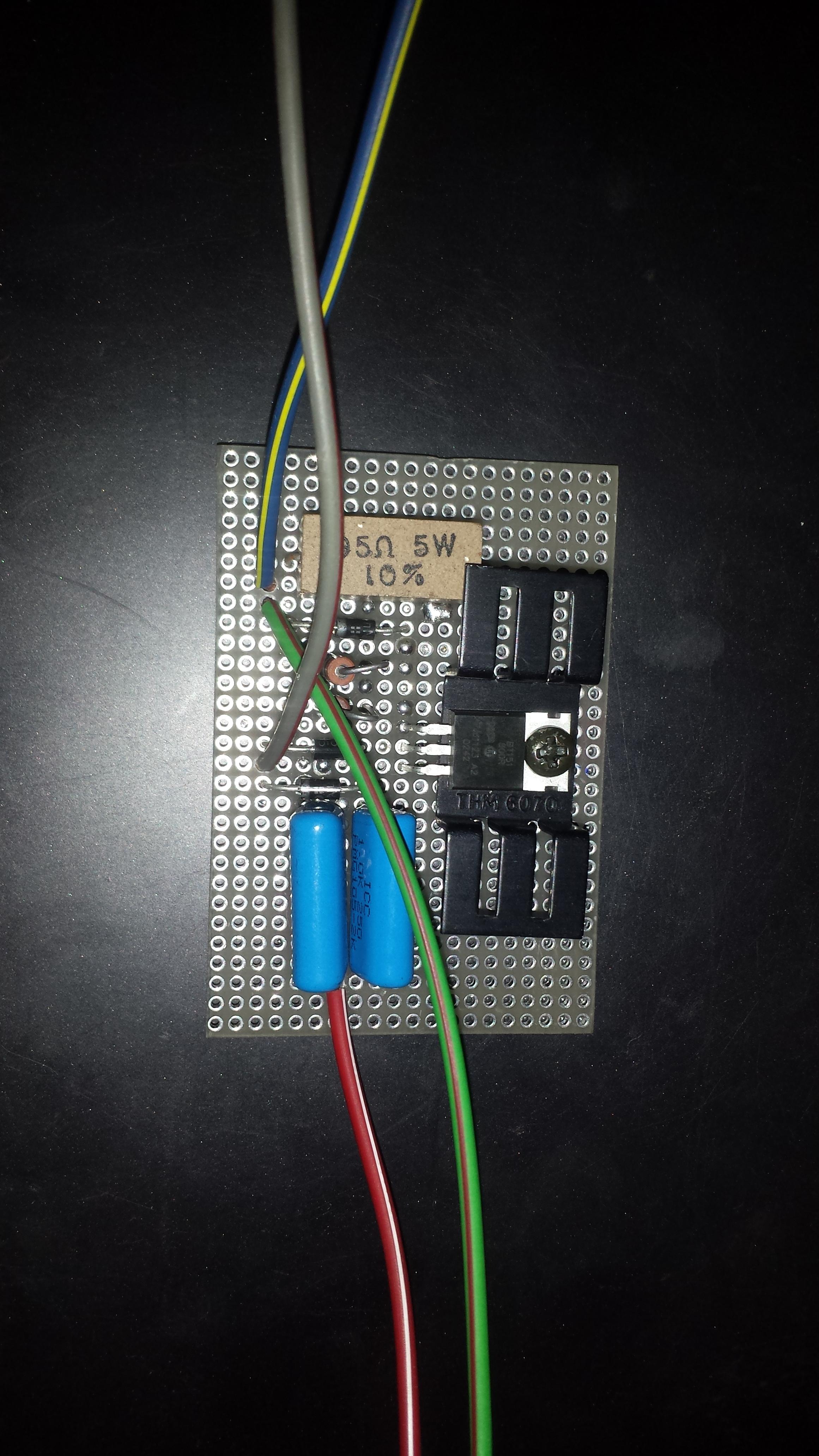
I finally built one, I saw this thread years ago and finally got around to it. My only concern is that I used a pair of 250V caps. Am I doomed to a CDI that fails? What I don't understand is I thought the caps were the place where the voltage is really multiplying from whatever the magneto puts out to what goes into the ignition coil. If that's the case then why is it bad to use a lower voltage cap? Someone please explain what's going on and if I need to swap the caps out before I test it.


WECSOG

Member
Nov 10, 2014
138
13
18
North Alabama, USA
250 volt caps will probably be fine. It is doubtful that the stator on these engines will produce much more than 200, anyway.
There is no voltage increase inside the CDI. The stator outputs around 200 volts AC which is rectified to DC and stored in the cap until the right moment when the SCR triggers and dumps the charged cap into the coil primary. Cap voltage is whatever the stator outputs.
 

LS614

Active Member
Dec 22, 2009
1,236
3
38
CT and MA
Thanks for the reply! Is there any measure I could/should take to protect the caps or should I just try it out and see what happens? The explanation of what specifically is going on helps a bunch. :)
 

LS614

Active Member
Dec 22, 2009
1,236
3
38
CT and MA
Hey guys, so an update. I took the magneto cover off and put a 14mm socket on my drill, and hooked test wires up to my multimeter. My drill spins the engine around 750 to 1000 rpm, approximately idle speed. I found that my magneto generates 32.8 VAC consistently at idle speeds. I find it hard to believe that in normal operation I would be getting anywhere close to 300 VAC from the magneto coil. So I tested the circuit using more test leads and my drill and here is the result. A nice fat blue spark. Thank you to everyone who helped fine tune this circuit.

https://www.youtube.com/watch?v=FQcmAN0XSJI
 
Last edited:

WECSOG

Member
Nov 10, 2014
138
13
18
North Alabama, USA
I would just try it and see what happens. The only way you could really protect the caps would be to add resistance to the circuit, and that would introduce several additional problems.
Even if the caps blow (which I think is unlikely), it shouldn't take anything else out. You should be able to just replace the caps and be good to go again.
 
Last edited:

Ahmedy

New Member
Nov 2, 2015
20
0
0
South Africa
Hi guys. I've got a problem. I've built Rohmell's cdi twice now and I tried building the jag one also. I'm not getting spark from either. Then when I hook up the original Cdi it works with no problem. Could it be the Chinese coil I'm using or could it be that the original stator coil isn't producing enough volts.
 

nyemi

New Member
Feb 16, 2014
3
0
1
Hungary
Welcome everyone.
Circuit your opinion?
Resistance(P1) to change the ignition timing.
Your test circuit.zpt

Regards nyemi


Postscript:I optimize circuit.Sorry.
 

Attachments

Last edited:

humanj

New Member
Nov 1, 2016
2
0
0
George
Hi Rohmell

Please help me out, I noticed in the first circuit you posted a 33 Ohm resitor was present. The later circuits it is not present. At first I tried the circuit with the 33 Ohm resitor but no spark. Eventually I came right after removing it. Is the purpose of this resistor the limiting of current on the Gate Resitors?

I must say this circuit performs very well givven its simplicity. I used a Yamaha Generator Ignition Coil.

Thanks for your effort!!
 

Attachments

humanj

New Member
Nov 1, 2016
2
0
0
George
Hi Toad

You can use a Yamaha Generator coil -- Yamaha High Voltage Set ET950 -- Works well.

In the orginal Circuit you added another capacitor but you did not include the capacitance value. I would also like to experiment, please supply the vallue.

The orginal circuit works well I must say.
 

Attachments

Miguel P

New Member
Sep 10, 2017
13
0
1
31
Anyone around that can check the adequacy of this parts list for the kdx200 type CDI. The two last capacitors have higher rating than the first three but the first are specified to be for high frequency applications.. Which should he favored I wonder?

TIRISTOR (SCR) TIC106D 400 PIV 5A

Metallic film resistors 33R 1W ±5% Ø4x10mm 82R 1W ±5% 390R 1W ±5% Ø4x10mm 1.5kR 2W ±5% Ø5x12mm 1.8kR 2W ±5% Ø5x12mm 150R 2W ±5% Ø5x12mm 470R 2W ±5% Ø5x12mm

Capacitor polypropylene 0.47uF 400VDC/250VAC RM27.5mm impulse resistance 400V/us
Capacitor polypropylene 1.5uF 400VDC/250VAC RM27.5mm impulse resistance 200V/us
Capacitor polypropylene 4.7uF 630VDC/280VAC RM37.5mm impulse resistance 120V/us

Capacitor polypropylene 1.5uF 560VDC/275VAC RM27.5mm
Capacitor polypropylene 0.47uF 630VDC/280VAC RM22.5mm impulse resistance 200V/us

Rectifying Diodes 1000V 3A - 1N5408
 

junglepig

Member
Oct 28, 2018
78
32
18
Georgia
Hi. I'm a newbie here. I completed my one and only build about a month ago.
I'm an engineer (chemical and controls, not exactly electrical, but I manage OK) and I'd like to experiment with building my own CDI with some tuning capability. There is a lot of info here, but it is spread out among several forums and threads, and I wonder if someone could point me to the most efficient place to start. Also, many of the old posts have broken links to images, which make it impossible to read and follow the discussion and development.
I will happily share any information I learn or develop. I'm a big believer in open-source design.
Also, as an electronics hobbyist, I have a good 2-channel oscilloscope and I'd love to put it to use to measure the performance and function of our CDI circuits.
Let me start by asking: What is the most current, best developed DIY CDI circuit that members have built, tested, and are using happily on their own bikes?