modified cdi and cr 80 coil

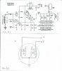
Hi Dracothered, that CDI is pretty much the standard basic design used on most 4 stroke singles. 5 wires being 1 high voltage AC input from the magneto stator coil, 1 input from the triggering coil, a ground connection, 1 wire for the kill switch & an output to the ignition coil. The CDI kit from Jaycar (www.jaycar.com.au, Cat No.KC-5466) is exactly suited to this application. I built one about 3 years ago for a friends small 4 stroke single after his failed & he found the price of an OEM replacement was rediculous. The kit CDI is a 5 wire type & the cost was around AU$22-00 about 3 years ago so it would be around the same or a couple of bucks more at the most & could be shipped in a small parcell post envelope so shipping would be very cheap. I think the schematic & kit construction notes etc are available online from Jaycar, I'll find out for u & get back to u. I thought I had the schematic from the kit but havent yet found. I may have given it to ol' mate when I gave him the CDI. The Honda 90 CDI is a simple 2 input wire & 1output to the coil (3 wire) type. It would most likely still work to some degree in ur application & could be easilly hooked up (1 lead to the stator, 1 to ground & 1 to the coil) tho it may not make use of the advance mechanism. The schematic for this CDI I got from the "Roll ur own CDI" thread in the lighting & electrical section. Hope this helps.
EDIT
I just did a quick google search, typed in "Jaycar CDI kit Cat No. 5466 schematic & kit construction instructions" & then clicked on "Repiacement CDI Module For Small Petrol Motors- Silicon Chip". There is an excellent article from the Silicon Chip magazine here that gives details on the design of the CDI as well as how it works, a schematic diagram, layout etc etc, as well as links to a couple of downloads. I imagine u could easily build 1 from the info there without needing to worry about obtaining a kit. Hope this helps. Cheers
 
Last edited:
Hi, a couple of posts back I said if anyone was interested I would post how to go about modifying the CDI circuit to suit ur motors exact needs. Well as I'm sitting on a bus with nothing to do I'll give u the lowdown. Ok so we'll start with setting the initial firing point, which also determines the positioning of the whole timing curve. Normally, using the stock Jag spec u have a choice of just the 16 ohm pulldown resistor, or u can jumper in the 220 ohm, or u can jumper in the 120 ohm resistors. So wot jumpering these resistors in is doing is putting them in parallel with the 16 ohm resistor & thus lowering its value. Paralleling 16 & 220 gives a value of 14.915 ohms & paralleling 16 & 120 gives 14.117 ohms. So lowering the value of the pulldown resistor RETARDS the timing. This also works the other way. Increasing the value of the 16 ohm pulldown resistor ADVANCES the timing. DO NOT DO THIS UNLESS U KNOW HOW TO DIAGNOS AN OVER ADVANCED CONDITION. MOTOR DAMAGE CAN RESULT OTHERWISE. So wot I do is to replace the 16 ohm with an 18 ohm. To give u an idea, paralleling a 150 ohm with this 18 ohm gives a resistance of 16.071 ohms, or so little of an advance over the stock 16 ohm with no resistor jumpered in that u wouldnt notice it. Now paralleling the 220 ohm with the 18 gives a value of 16.638 ohms, which will advance ur timing a couple of degrees over that of the stock 16 ohm. Paralleling the 120 ohm with 18 ohms gives 15.652 ohms, which is about,,, a bit less than a degree retarded of just a 16 ohm resistor. So by paralling different values u can move the initial firing point, & with it, the whole timing curve. If u google "Parallel Resistor Calculator", u'll find a calculator that u can type different values into, then hit calculate to get an exact value. U can then use this to help u find which values to use instead of just the normal values of 220 & 120 ohms, to get ur timing where u want it. U dont need to change the pulldown resistor from 16 ohm to 18 ohm to do this. The general idea is a bigger resistor in parallel with the 16 ohm reduces the value a little, & a smaller rrsistor in parallel with it reduces the value more. I use the 18 ohm so that I can advance it a bit. Well, I'm nearly at my stop so in the morning I'll post how to use different value timing caps to make the hi rpm retard curve either more, or less steep than wot just the stock jumpers offer. Cheers
 
Last edited:
Ok, so just to go back over, by first testing with standard values to find where ur best state of tune is, then with a little thought, calculating & testing, u can fine tune. Suppose u find that by adding the 220 ohm u get better lo end power than without it, but if u add the 120 ohm u loose a little. So now u need to find which side of 220 ohms to go. Try 180 ohs. Still loose a little from wot 220 gives,., try 250 ohms. U just need to work oyt whicg way u need to move ur timing for optimum, & only move it a little at a time. Its simply a matter of testing, testing, testing, & using common sense. U can also make up in between value resistors by paralleling a couple, or putting them in series to make a value u need. The inly thing with putting them in series is that this ADDS THEIR VALUES TOGETHER, eg 68 ohm in series with 56 ohm gives 124 ohms. Ok, when u have the low end at its optimum u will want the hi end set as best as u can. Normally u have a 4.7uf tantalum cap soldered in place with its + marked leg going to ground & two 0.47uf tantalums that u can jumpet their + marked legs to ground. Again, jumpering these in is simply putting all of them in parallel, however unlike resistors in parallel, putting capacitors in parallel ADDS THEIR VALUES TOGETHER. Now, to fine tune the high RPM retard curve u take the same aproach as when u did the lo rpm setting, but u will first want to have a few different small value tatalums on hand. The common values u will want are 0.10uf,., 2 of these
0.22uf,,, 1 of & 0.33uf,,, 1 of. Now u can cover the range between adding 1 x 0.47uf & adding 2 of, plus more. So u take the same approach again. No matter wot setting u find gives the best hi end performance with the normal values, then work out which way u need to go to get the most out of it, (tho u may b lucky & find one of the standard values gives this). Say u find that the both 0.47uf caps jumpered in gived best top speed. To work out which way to go, add a 0.22uf, test, then remove the jumper from one 0.47uf while leaving one 0.47uf & the 0.22uf there. Its the same process, work out which way u need to go by testing, a bit of thought, more trial & error testing using smaller values each time to find the sweet spot. This is fine tuning the steepness of the hi RPM retard curve that starts to kick in at around 2/3 max rpm, roughly. I wont go into moving the point at which the hi rpm retard curve kicks in here tho it is possible. Hopefully this info might be usefull to some of u racers looking for the best level of tune possible from ur motor & are prepared to spend the time testing & testing again to achieve it. I would reccomend that u get all other motor mods done before fine tuning ur CDI, or u'll need to redo it every time u do another mod. Sorry about all the typing errors, damn PITA touch screen phone POS. Should anyone want to ask any questions on fine tuning a CDI u can PM me & then do it all by email. It really isnt that hard to do, just a bit time consuming but like getting anything right with ur motor, the resilts ate worth it once u get it right. Cheers.shft..shft.
 
Last edited:
I am having a some problems with my cdi.

I get one spark and thats all.

to start, i was riding my bike and all of a sudden i lost spark.

i know i dont have spark as i have a tack/hour meter for an rpm read out and engine hour meter. So, replaced the coil and still no spark.

I purchased a new SCR and replaced it and no spark.

So I decided to make a new circuit. I had spare components bar the big capacitors. Now, i get one spark, each time i turn the engine over. thats all. i will stop for a few seconds and start turning again, get one more spark. And its a very weak spark as well. I can hardly see it.

I have been running using the stock cdi, and it has a much bigger spark.

I will purchase some new caps tomorrow to see if they are the problem.

One funny thing, I have noticed when putting my ohm meter across the 1k (1% and 1/2 watt) it sometimes reads 760ohms?? is this normal? I stick the meter wires right across the resistor. However, sometimes it reads 960ohms.
Maybe, my meter needs to replaced as well. I am taking into account the resistance of the contact between the probes and the dirt on the resistor legs.

any help welcome.
 
here is a pic on of the CDI I made.

180820134501_zpsf45ddcbc.jpg


fully adjustable. lots of trouble.
 
Hi Everybody

This is my first post here.

I have been working on CDIs for 2-stroke motorbikes, with 4/5 wires. I have been looking for curve advancement. There are a few micro controller based programmable CDIs but I am looking for some analog circuit. I came across the JAG high RPM analog CDI and also its cloning + enhancement here at this forum. But I see that JAG cdi has only 3 wires! HV from the alternator, Ground and the output to the ignition coil. I wonder, how this CDI gets trigger.

Maybe the motorized bicylces have some different system. I would like to know if these CDIs can be used, with some mods, for 2-stroke motorcycles to have switchable curves?

Valued suggestions would be highly appreciated.
 
Last edited:
There are a few micro controller based programmotorized bicyclele CDIs but I am looking for some analog circuit.

This line should be read as

"There are few micro controller based program-able CDIs but I am looking for some analog circuit."

I have tried to edit it but the correction is not made!
 
Last edited:
Hey, hoping somebody might still be around that could help me! I've put together a cdi pretty much exactly as Draco laid out in his post. Yet I am getting no spark. So I double checked everything and found out that one of my tantalum capacitors was backwards, but still nothing. Sooo I made a 2nd one (seemed to be better made than the first), as close to the design as I can possible make and still nada. Yet when I put my old "simple cdi" back on, sparks perfectly. Please, somebody take a look at my pics and tell me what ya think! (the brown wire in the upper left is supposed to be the red) lol.....hugely frustrated.


The rocket cdi is a very compact version of this.
At a reasonable price.
And is non encapsulated, so can be modified to suit.
 
Minus all of the satisfaction of learning and building one yourself (....only to have it not work....help...) Not to mention the cost savings and the added benefit of possibly being able to fix it yourself if ever need be.

And yes, I would be willing to make and sell a couple if I can just work out the kinks and get it working!
 
Try buying new caps.

This happened to me, no spark that is. I rebuilt the circuit and still no luck.

Replaced the caps. and spark spark spark.
 
Circuit diagram
attachment.php


Here is the Board Layout from the parts side.

attachment.php


Foil side of the board

attachment.php


Modified CDI parts list.

5ea 1N4007
SCR,C106D,4A,400V,TO-202AB CASE
http://www.jameco.com/webapp/wcs/stores/servlet/ProductDisplay?freeText=C106D&langId=-1&storeId=10001&productId=160119&search_type=jamecoall&catalogId=10001&ddkey=http:StoreCatalogDrillDownView

Resistor ½ watt 1% Metal film
16
27
33
100
120
220
390
760
1K

Capacitor
2ea 0.47uF 35v Tantalum
2ea 0.47uF 275v Polypropylene
4.7uF 35v Tantalum

Jumpers
5ea 3 pin male jump, (HEADER,.1 INCH STRAIGHT MALE)
http://www.jameco.com/webapp/wcs/stores/servlet/Product_10001_10001_109576_-1

5ea Connector Shunt Female 2 Position
http://www.jameco.com/webapp/wcs/stores/servlet/Product_10001_10001_793792_-1

Heat sink (NOTE: ONLY NEEDED IF SCR IS A TO-220 PACKAGE)
http://www.jameco.com/webapp/wcs/stores/servlet/Product_10001_10001_326596_-1

NOTE: All parts listed with URL's are examples of what you need.


Good evening , congratulations for your article, kindly ask for your help because I would like to install the unit on a bike. In my motorbike with two stator windings, one ac generator coil and pulser coil as shown in figure(1). just connect them as figures (2)? or you tell me how to do. Many thanks .
 

Attachments

  • 6B68E4BBB16748E68CEDFE3C755680BC.jpg
    6B68E4BBB16748E68CEDFE3C755680BC.jpg
    113.4 KB · Views: 930
Thank you all! Now for testing...
 

Attachments

  • IMG_20171125_235835_6.jpg
    IMG_20171125_235835_6.jpg
    101.8 KB · Views: 779
  • IMG_20171126_234059_2.jpg
    IMG_20171126_234059_2.jpg
    81.8 KB · Views: 785
  • IMG_20171126_232932_6.jpg
    IMG_20171126_232932_6.jpg
    95.7 KB · Views: 766
  • IMG_20171126_233748_8.jpg
    IMG_20171126_233748_8.jpg
    108.1 KB · Views: 681
Back
Top