
You are using an out of date browser. It may not display this or other websites correctly.
You should upgrade or use an alternative browser.
You should upgrade or use an alternative browser.
modified cdi and cr 80 coil
- Thread starter damo99
- Start date
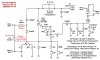
Hey Dracothered, I hate 2 do this 2 u, u've done such a good job & I shoulda picked it up b4 (my bad eyes & small screen phone dont help)' but move the end of the 33 ohm resistor closest 2 the kathode of the SCR to the junction of the 1K resistor & the 390 ohm resistor. Sorry mate, u really have done a great job. Cheers
dracothered
New Member
Hey Dracothered, I hate 2 do this 2 u, u've done such a good job & I shoulda picked it up b4 (my bad eyes & small screen phone dont help)' but move the end of the 33 ohm resistor closest 2 the kathode of the SCR to the junction of the 1K resistor & the 390 ohm resistor. Sorry mate, u really have done a great job. Cheers
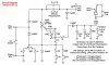
No problem all fixed, see the above circuit drawing...
Huffydavidson
STREETRACER/MANUFACTURER
I want one. Please let me know.
U have 2 build urself, its only a few bucks in components, plus an external coil which u can get for around 25 bucks for a good 1. I'll put a new 1 together as developed by Dracothered next week when the electronics store is open & try to get pics of both sides of posted (I'll have 2 get some1 to do 4 me as its above my capability) so people can c the layout. Its pretty simple really. Cheers
dracothered
New Member
I'm working on a layout drawing also, it is almost done.
Huffydavidson
STREETRACER/MANUFACTURER
Ok, kool stuff! I don't know anything about electronics but got a fellow rider that does. A parts list would very help full. I have any electronics surplus store 3 blocks from my house . I have a jaguar cdi I bought 3 months ago and I'm very pleased with the performance of it. I have almost no vibration at 7500rpm.s . My other bike run great but it will Reallllllyyyyyy fly smooth with a shall we say a clone CDI on it! Thanks for your excellent research and work.
dracothered
New Member
Circuit diagram

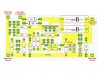
Here is the Board Layout from the parts side.

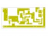
Foil side of the board

Modified CDI parts list.
5ea 1N4007
SCR,C106D,4A,400V,TO-202AB CASE
http://www.jameco.com/webapp/wcs/stores/servlet/ProductDisplay?freeText=C106D&langId=-1&storeId=10001&productId=160119&search_type=jamecoall&catalogId=10001&ddkey=http:StoreCatalogDrillDownView
Resistor ½ watt 1% Metal film
16
27
33
100
120
220
390
760
1K
Capacitor
2ea 0.47uF 35v Tantalum
2ea 0.47uF 275v Polypropylene
4.7uF 35v Tantalum
Jumpers
5ea 3 pin male jump, (HEADER,.1 INCH STRAIGHT MALE)
http://www.jameco.com/webapp/wcs/stores/servlet/Product_10001_10001_109576_-1
5ea Connector Shunt Female 2 Position
http://www.jameco.com/webapp/wcs/stores/servlet/Product_10001_10001_793792_-1
Heat sink (NOTE: ONLY NEEDED IF SCR IS A TO-220 PACKAGE)
http://www.jameco.com/webapp/wcs/stores/servlet/Product_10001_10001_326596_-1
NOTE: All parts listed with URL's are examples of what you need.
Here is the Board Layout from the parts side.
Foil side of the board
Modified CDI parts list.
5ea 1N4007
SCR,C106D,4A,400V,TO-202AB CASE
http://www.jameco.com/webapp/wcs/stores/servlet/ProductDisplay?freeText=C106D&langId=-1&storeId=10001&productId=160119&search_type=jamecoall&catalogId=10001&ddkey=http:StoreCatalogDrillDownView
Resistor ½ watt 1% Metal film
16
27
33
100
120
220
390
760
1K
Capacitor
2ea 0.47uF 35v Tantalum
2ea 0.47uF 275v Polypropylene
4.7uF 35v Tantalum
Jumpers
5ea 3 pin male jump, (HEADER,.1 INCH STRAIGHT MALE)
http://www.jameco.com/webapp/wcs/stores/servlet/Product_10001_10001_109576_-1
5ea Connector Shunt Female 2 Position
http://www.jameco.com/webapp/wcs/stores/servlet/Product_10001_10001_793792_-1
Heat sink (NOTE: ONLY NEEDED IF SCR IS A TO-220 PACKAGE)
http://www.jameco.com/webapp/wcs/stores/servlet/Product_10001_10001_326596_-1
NOTE: All parts listed with URL's are examples of what you need.
Attachments
Last edited:
Well done Dracothered. This really is a big + for everyone as the CDI does make the motor run much smoother right thru the rev range with a hotter spark (depending on coil used, CR80 coil gives hottest), while developing better low RPM power & allowing it to rev much higher. U dont need electronics knowledge to put it together, & if u run into any problems dont hesitate to ask questions. Cheers
dracothered
New Member
Well done Dracothered. This really is a big + for everyone as the CDI does make the motor run much smoother right thru the rev range with a hotter spark (depending on coil used, CR80 coil gives hottest), while developing better low RPM power & allowing it to rev much higher. U dont need electronics knowledge to put it together, & if u run into any problems dont hesitate to ask questions. Cheers
I do hope that someone that has a bike could build one of these and test it out as I right now don't have a bike to use it on. I would be willing to build one for someone, but I can't do it for free and really we need a test bed one first before a final build one can be built.
Hi Dracothered, I have 1 of each type 4 my bike & have built a couple 4 other people. I had planned on putting 1 of the 1's as u've developed during the last week but havent had time to get to the local electronics outlet. I'll get there in the morning & grsb a bit of prototype board, SCR & the caps & put 1 together. I've got plenty of 1/2 watt metal film resistors. Hopefully I'll have enough time over the weekend. Cheers
soup325
Member
Hi all,
Im trying to find a SCR C106D that is 600v 8A.
But im finding it hard.
Would a C106M1 or a C122E do?
http://www.jaycar.com.au/productView.asp?ID=ZX7012
http://www.jaycar.com.au/products_uploaded/C106-D.pdf
an SCR C106D but 4A and 400v
http://www.jaycar.com.au/productView.asp?ID=ZX7006
any help would be great. im still in the 'finding all the parts' stage
dracothered
New Member
Hi all,
Im trying to find a SCR C106D that is 600v 8A.
But im finding it hard.
Would a C106M1 or a C122E do?
http://www.jaycar.com.au/productView.asp?ID=ZX7012
http://www.jaycar.com.au/products_uploaded/C106-D.pdf
an SCR C106D but 4A and 400v
http://www.jaycar.com.au/productView.asp?ID=ZX7006
any help would be great. im still in the 'finding all the parts' stage
This one would be a better choice or one similar.
http://www.jameco.com/webapp/wcs/stores/servlet/Product_10001_10001_14761_-1
Also used with this type of heat sink.
http://www.jameco.com/webapp/wcs/stores/servlet/Product_10001_10001_326596_-1
Hi, I've been using C106D1, Vmax 400, IE(A) 4, VF(V) 2.2, IG(uA) 200, VG(V) 0.8, Hold In(mA) 3. If u can get an industrial rated C106D1 SCR they r much better quality & have way better thermal characteristics, but just an ordinary old C106D1 will b fine usually. I havent had 1 fail & dont heatsink them. I was going 2 put 1 together over the weekend but the local outlet is outta polypropylenes so it'll b a couple of days. Cheers
dracothered
New Member
Hi, I've been using C106D1, Vmax 400, IE(A) 4, VF(V) 2.2, IG(uA) 200, VG(V) 0.8, Hold In(mA) 3. If u can get an industrial rated C106D1 SCR they r much better quality & have way better thermal characteristics, but just an ordinary old C106D1 will b fine usually. I havent had 1 fail & dont heatsink them. I was going 2 put 1 together over the weekend but the local outlet is outta polypropylenes so it'll b a couple of days. Cheers
Have you ever touched the SCR after running it for a while, was it warm to the touch or to hot to touch for very long? But it is good to hear that you haven't had one fail yet.
The one I listed which is in a 220 package style if I remember right I like better because it has the tab which is like a small heat sink its self.
Last edited:
soup325
Member
hanks Dracothered and Ivan.
Im trying to buy local (OZ), if I can. Let alone trying to by it in Canberra as it is very hard, as there is very little options in terms of industrial suppliers here.
I like the sound industrial rated stuff. any links or contacts? do any of the following links provide any industrial product standard?
http://www.electusdistribution.com....ATID=33&keywords=&SPECIAL=&form=CAT&SUBCATID=
http://australia.rs-online.com/web/p/thyristor/6254988/
http://www.tech4u.com.au/c106d1-400v-4a-scr-p207114.html
also, I might buy this PCB etching kit to build my board
http://www.tech4u.com.au/pcb-etching-kit-p203556.html
Hi, yes, I've felt all components, after hour plus ride. They dont even get warm. As I posted, a C106D1 is a 400V, 4A SCR & its only passing spikes, not continuos current. 1/2 watt resistors say it all really, & they dont get warm. Kawasaki used a C106D1 unheatsinked in the origonal CDI. U should have no problem getting all components in Canberra, I posted Jaycar catalogue No.s a few posts back 2 make it easy 4 people in Oz. Cheers
C post 210 for Jaycar catalogue No.s. I do think it will b possible 2 run 2 far advanced without care with this setup, but I've told how 2 check 4. I've been running these 4 a long while & the most advanced I've used is with 27 ohm pulldown & 1k & 100 ohm in series between kathode & gate. Cheers