
You are using an out of date browser. It may not display this or other websites correctly.
You should upgrade or use an alternative browser.
You should upgrade or use an alternative browser.
49cc's on a Schwinn
- Thread starter FOG
- Start date
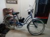
Got my offset motor mount welded up which means it's finally time for paint. That blue and primer with red wheels motif isn't gonna be missed.
That means stripping the frame and some YouTube time over the kickstand. On Schwinn's there's a spring inside the barrel that the kickstand rotates in, and that's held in place by a small pin. Once the spring is compressed the pin comes out and it's done.
Compressing the spring is the tricky part and there's a $45 tool available, but that don't make any sense. How often would I need that?
So instead I fired up the lathe and made small ring to fit over the kickstand, gave it a squeeze to compress the spring with my channel locks, and the pin came right out. That was easy.
![DSCF0859[1].JPG](https://motorbicycling.com/data/attachments/92/92991-33ff48567c1cd868a912f99ca360f357.jpg?hash=M_9IVnwc2G "DSCF0859[1].JPG")
That 67 y/o lathe just earned me another $45.
That means stripping the frame and some YouTube time over the kickstand. On Schwinn's there's a spring inside the barrel that the kickstand rotates in, and that's held in place by a small pin. Once the spring is compressed the pin comes out and it's done.
Compressing the spring is the tricky part and there's a $45 tool available, but that don't make any sense. How often would I need that?
So instead I fired up the lathe and made small ring to fit over the kickstand, gave it a squeeze to compress the spring with my channel locks, and the pin came right out. That was easy.
That 67 y/o lathe just earned me another $45.
tommyboy1442
Member
tommyboy1442
Member
Apologies for cutting in. Really do dig your project. Turning out real nice.
I've got 2 motors to work with, or I should say had. One's got a cracked jug and my Grandson wore the chrome outa the other one when it was in his mini quad. He was a mechanically abusive child. ")
Not a problem tho. A top end with piston, rings, pin, gaskets, and even a new coil is only $25. In this modern world Chinese labor makes a poor boy's dollar go a long long way ...
I get to pick between a 40mm or 44mm and the pocket bike guys tell me they like the 40. No de-compression notch above the exhaust port and thicker cylinder walls means deeper boost ports.
It's only available in a 1 piece jug tho which makes setting the squish band and getting the compression right just about impossible. Solution? Chop the head off! Yeah! Make it a 2 piece myself. I already decapitated the scrapper for practice.
My hacksaw's ready. I just need my parts to get here.
In the beginning ...

And ... Off with her Head!!!

That's a conservative cut. Bit on the cowardly side really, but ya can't put the metal back on.
I had to get the cylinder straight with the spindle to know I was getting a perpendicular cut across the top and centered with the bore at the same time. Being off by as much a .010 probably wouldn't have mattered but I fussed with it until it was inside .001.

And done.

And ... Off with her Head!!!
That's a conservative cut. Bit on the cowardly side really, but ya can't put the metal back on.
I had to get the cylinder straight with the spindle to know I was getting a perpendicular cut across the top and centered with the bore at the same time. Being off by as much a .010 probably wouldn't have mattered but I fussed with it until it was inside .001.
And done.
Due to the location of the ring pins there's a lot of real estate on the backside of this cylinder, so I learned myself how to make dual boost ports.

I really shouldn't say ports. Except for the exhaust this funny little motor's all about slots! I do like the way the main transfer "slots" are angled to the back tho. Adolf Schnuerle would be proud.
Being concerned about the boosters shootin' the charge right across the top of the piston and out the exhaust I ground a lotta radius into the cutter.

Next I gotta work on positive cylinder location. The hole in the cases is way bigger than the jug. No dowels. 4 screws and wherever it lands ...
I really shouldn't say ports. Except for the exhaust this funny little motor's all about slots! I do like the way the main transfer "slots" are angled to the back tho. Adolf Schnuerle would be proud.
Being concerned about the boosters shootin' the charge right across the top of the piston and out the exhaust I ground a lotta radius into the cutter.
Next I gotta work on positive cylinder location. The hole in the cases is way bigger than the jug. No dowels. 4 screws and wherever it lands ...
indian22
Well-Known Member
Fog are you making a head or repurposing one? Cylinder studs double duty as head bolts? Nice work on the cylinder & milling of the two transfer ports is well done and should show some power gain. Are you going with reed valve & piston window as well?
I like the time your investing in this motor as I'm really not a fan of these one piece jugs that require popping the motor off for simple upper cylinder work or service, let alone the reasons you've mentioned.
Rick C.
I like the time your investing in this motor as I'm really not a fan of these one piece jugs that require popping the motor off for simple upper cylinder work or service, let alone the reasons you've mentioned.
Rick C.
Yeah. You guessed it Rick! I'm thinking about making my own cylinder head. 1st I have to design and build an appropriate radius cutter for the chamber dimensions. That'll keep my brain fizzin' for awhile.
On head studs one of my shortcomings is in 1952 America when my lathe was new metric was still a foreign language. I can't cut an M6 X 1.0mm thread. But I can tap it so I'm thinking countersunk nuts on top of matching cuts in the cylinder base riding on the 4 head bolts. That should lock the jug down in the same place every time.
This is a case inducted motor, no intake port at all, so reeds are the only option. I am planning on a pair of indexed holes in the back of the piston to feed the boost ports tho. The "slots" are only .150 deep. I can't imagine a lot of air will get up past the piston without some holes to help fill them.
Doing all I can to get all I can get out of all 47cc's! I dunno why. But it makes me happy.
indian22
Well-Known Member
Yeah. You guessed it Rick! I'm thinking about making my own cylinder head. 1st I have to design and build an appropriate radius cutter for the chamber dimensions. That'll keep my brain fizzin' for awhile.
On head studs one of my shortcomings is in 1952 America when my lathe was new metric was still a foreign language. I can't cut an M6 X 1.0mm thread. But I can tap it so I'm thinking countersunk nuts on top of matching cuts in the cylinder base riding on the 4 head bolts. That should lock the jug down in the same place every time.
This is a case inducted motor, no intake port at all, so reeds are the only option. I am planning on a pair of indexed holes in the back of the piston to feed the boost ports tho. The "slots" are only .150 deep. I can't imagine a lot of air will get up past the piston without some holes to help fill them.
Doing all I can to get all I can get out of all 47cc's! I dunno why. But it makes me happy.
Good solution on tapping & countersinking & thought I was looking at case inducted jug, but wasn't 100% certain. The window holes in the piston and the added ports should perk it up.
Rick C.
I used some 10mm stainless hexstock to make beveled nuts to ride down the head bolts and sit in countersinks in the base of my cylinder.

But there's a problem. All 4 won't sit in the sinks at the same time! Turns out the threaded holes in the cases aren't square.
I'm cool with this. The original design and intent doesn't need that level of accuracy. It'll still do it's job. But I'm gonna do things to this little motor the original design never intended. So I'll fix it.
My little mill can locate holes to .001 accuracy. A 1/4" end mill will "move' the holes over. And that's the hole size I need to tap for M6 heli-coils.
Now I'm wondering about head bolt torque. Surely a heli-coil can take more torque than aluminum threads. I did some google on the subject and got way to much information to wade thru for what I need.
Anybody got any ideas?
indian22
Well-Known Member
You're right FOG they will, when installed correctly, so coil away. Small motor aluminum is basically beer cans melted and repurposed. I've used these little jewels in many "high quality" aluminum automotive heads without a problem, if anything they are better than the "original high quality" aluminum which pulls and fails frequently. Guess what? Dealers won't install heli's in factory warranty work gotta' have a new head , they tell say, etc. but then they repair those heads with heli's and later use them on out of factory warranty period customer rebuilds as "rebuilt" replacement parts with exchange, and include a 90 day warranty on the job and the cycle continues. Larceny lurks in the hearts of man!
Rick C.
Rick C.
Got my heli-coils in and it turns out there was just one threaded hole that was off. I got to using a precision square to pick a hole for a datum to start from and found 3 of them were 90 degrees and 44mm apart. That other bugger was the .020 variation.
100 in/lbs of torque is good to go.
From there I got to looking at my balance factor using this link from one of the pocket bike guys.
Had to knock out a quick balancing stand to do it.

This is an interesting subject in that vertical and horizontal cylinders need to be balanced differently. It seems this is all about controlling the direction of the vibration instead of eliminating it. A single cylinder motor is gonna vibrate no matter what you do. But a fore and aft horizontal vibration makes for a smoother ride. It's up and down vibration that'll get the bars buzzin'.
At the typical 55% in a vertical it's the counterweight that's in charge which produces vibes in the horizontal direction.
Being already horizontal with only 43% of counterweight the piston is what vibrates my little motor.
Who knew?
100 in/lbs of torque is good to go.
From there I got to looking at my balance factor using this link from one of the pocket bike guys.
Had to knock out a quick balancing stand to do it.
This is an interesting subject in that vertical and horizontal cylinders need to be balanced differently. It seems this is all about controlling the direction of the vibration instead of eliminating it. A single cylinder motor is gonna vibrate no matter what you do. But a fore and aft horizontal vibration makes for a smoother ride. It's up and down vibration that'll get the bars buzzin'.
At the typical 55% in a vertical it's the counterweight that's in charge which produces vibes in the horizontal direction.
Being already horizontal with only 43% of counterweight the piston is what vibrates my little motor.
Who knew?
Being a case inducted motor with a half circle crank acting like an egg beater the PB guys tell me smooth air flow thru the top of the case leads to substantial gains. Here's a stock pic. Top of the case is on the left side ...

Definitely convoluted where the cylinder meets the case.
My dremel skills do not include boost ports, but carving a case ain't so hard. After cutting an airflow path and filling corners with epoxy I have both case halves looking like this ...

It's a smooth criminal now.
Definitely convoluted where the cylinder meets the case.
My dremel skills do not include boost ports, but carving a case ain't so hard. After cutting an airflow path and filling corners with epoxy I have both case halves looking like this ...
It's a smooth criminal now.