3 speed Elgin Velocipede 1934

GoldenMotor.com

silverbear

The Boy Who Never Grew Up
Jul 9, 2009
8,325
670
113
northeastern Minnesota
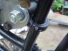
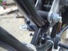
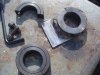
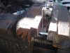
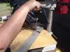
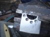
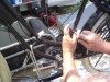
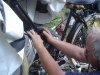
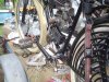
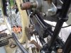
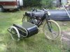
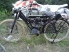
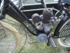
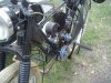
Here are a few more photos. The first shows the rear mount which I finished making up this morning. It is much like the front mount shown in the second photo, but modified so the engine can sit a little lower. Under each mount is a split collar. At the center of each mount is steel bushing which will be welded to one half of the split collar. Because the bushing can rotate it will conform to the angle of the frame and can be adjusted by loosening the split collar.

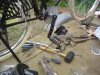
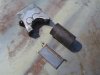
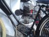
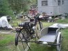
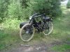
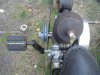
The third photos shows the pedal arms in black. They blend into the frame a little better I think.

As I wait for the second set of split collars for mounting the jackshaft to the front down tube I'll work on other things for this build. One is adapting the cable for the three speed hub to fit an old 1960's twist grip three speed shifter which looks like a throttle. I think it will be less conspicuous as a bike with gears with that type shifter. I also have to go over the front fender with some bondo and then fresh paint. And lots of other small, time consuming things... but each day and each task completed brings me closer to starting up the engine and putt putting off into the sunset. What fun!
SB
 

Attachments

harry76

Well-Known Member
Apr 16, 2011
2,557
47
48
Brisbane, Australia
I like your idea of turning down the engine crank attatchment to accept a pulley. Thats probably how i should have done mine, but instead i had a pulley threaded to the size of the crank thread. With your idea you will have more sideways adjustment as well as changing pulley sizes a lot easier if needed.

Ill have to revisit my pulley ratios and let you know what my reduction was. I think you would need/want lower gearing then i have as taking off can be a little awkward, but that could have just as much to do with the cramped feel of my ride, and having to try and take off with one hand on the tank mounted clutch arm, im 6'3 and pedalling can be a pain. I have a top speed of around 60kmh (37mph) which is a little faster then what you want anyway....... and besides these motors are just cool so you dont mind going a little slower, its such a nice ride.

I remember seeing this bike over on Ratrodbikes that has a clutch setup like we are talking about. Hope that helps. Its towards the bottom of the page, the bike doesnt belong to the thread, but has pictures from that poster.

http://www.ratrodbikes.com/forum/vi...id=e8462ed91bb882735a55143933c96f23&start=360
 

silverbear

The Boy Who Never Grew Up
Jul 9, 2009
8,325
670
113
northeastern Minnesota
Harry,
Thank you for the link. It does seem the best way to go and while I like the idea of a cool lever with ball on the end to relieve the tension on the belt, a locking clutch lever on the handlebar is the cleanest and simplest answer to the problem. Most important is that I know the direction of the build and that it will have a pulley and no centrifugal clutch.

Working out the pulley sizes is confusing at this point and I have no idea really. It is further complicated by the jackshaft to freewheel to rear wheel variables. At least if I get something wrong it can be tweaked and made right by changing pulley or sprocket diameters.

I'm also hoping (counting on) the three speed hub to compensate for the low revving of the engine. First speed is geared lower which should help in starting from a dead stop (without pedaling is the goal) and climbing hills. Second is as if there were no gears and third should help the top end so that I can cruise without winding out the engine (ideally at 25 to 30 mph). If I can avoid pedaling I'll be happy.

No work on the Elgin for a few days as I'm cutting and splitting firewood and Steve is adapting the mounts on my canoe sidecar to fit the Panther. The second set of split collars have arrived so next week we'll get one set welded to the jackshaft and the other set to the engine mounts. Then I need to get a pulley for the crankshaft and get the crankshaft attachment fitting turned down and a keyway made by someone.
SB
 

silverbear

The Boy Who Never Grew Up
Jul 9, 2009
8,325
670
113
northeastern Minnesota
We've made some progress on the Elgin now that the Panther has it's sidecar attached.

Steve's first attempts welding a steel plate to the split collar was not encouraging. Whatever finish was on the sides of the collars was not allowing the weld to penetrate and it looked like maybe they weren't going to work out after all. Bummer. A strong weld is absolutely essential since there would be just two mounting points to the frame for both the engine and for the jack shaft.

But we really wanted to use them since is seemed like such a good solution to the problem of leaving the original frame intact without alterations... no welding directly to the frame anywhere. The idea was that the original 1934 bike could be returned to it's original condition in spite of having been turned into a light motorcycle. It was beginning to look impossible. So we sat and stared until Steve got an idea.

He decided to try grinding away the case hardened surface of the split collar. That did it and subsequent welds had good penetration. To help make the union even stronger Steve drilled through the plate and into the collar in several places so the welds at those spots would beef it up more than just welding along the edges.
(cont.)
SB
 

Attachments

silverbear

The Boy Who Never Grew Up
Jul 9, 2009
8,325
670
113
northeastern Minnesota
The split collars are now welded to the steel plates, which in turn are welded to steel shafts which were part of the original engine mounts. With this done the engine can be firmly mounted to the frame. You can see why we think these split collars are a nice way to mount an engine without altering the frame. \(cont.)
SB
 

Attachments

silverbear

The Boy Who Never Grew Up
Jul 9, 2009
8,325
670
113
northeastern Minnesota
The engine is now mounted and the jack shaft assembly has been welded to Split collars at each end. Mounting the jack shaft behind the seat post would not work with this engine as the carburetor gets in the way. So we looked around for another option and settled on mounting it slightly forward and underneath the engine. As you can see in the photos it fits nicely between the two down tubes.

If it turns out that we need more room for the pulley on either the engine or the jack shaft then it can be mounted under the lower down tube. It can be adjusted forwards or backwards to tension the chain properly on the freewheel side of the bike. With the split collars tightened down both the engine and the jack shaft are rock solid. I couldn't be more pleased.

Now we need to determine the pulley sizes for the engine crankshaft and jack shaft. I'll be posting sizes of the other sprockets in the drive line tomorrow and will be asking for some help in figuring out what sizes the pulleys should be. When that's figured out the pulleys can be ordered.

I still have not come up with someone to turn down the crankshaft fitting to accept a pulley.

The throttle cable has been made up. Eventually I'll order a cable guide so that I have some adjustment. Being Whitworth threads it will have to be special ordered. I think it will work OK as I have it, but we'll see. I did put some gas in the tank and determined that the carb leaks. The gaskets may swell up and seal, but if not then I'll need to make some. I picked up gasket material today and new exacto blades. Once the carb doesn't leak we should be able to start the engine up using a belt as a pull start or possibly a drill with socket attached to the flywheel nut.

This project is coming along. Pretty soon we can pull the Indian Hiawatha out and get some work done on it, too The 50 Panther has it's canoe sidecar attached and has been turned into an "American Flyer". I'll post a thread on that soon. Maybe tomorrow. Busy summer...
SB
 

Attachments

silverbear

The Boy Who Never Grew Up
Jul 9, 2009
8,325
670
113
northeastern Minnesota
Thanks, Dan. It's coming along.

This is where I need some help from you gear heads out there. I need to figure out what size pulleys to order for the engine crankshaft and the engine side of the jack shaft. In reverse order here's what I have already. The pedal sprocket on the rear wheel is 13 tooth. From there to the freewheel sprocket receiving the jack shaft chain the chain ring is 44 tooth. On the other end of that chain at the jack shaft the sprocket is 9 tooth.

At this time there is a sprocket on the engine side of the jack shaft (17 tooth), but a pulley is going there in it's place. And a pulley will go on the engine crankshaft.

This is way beyond the capabilities of me little brain to cope with. Anyone have an idea of what pulley sizes I need? Keep in mind this is a slow revving engine and I have a three speed internally geared rear hub. I'm not looking for great speed, but low thirties in the top gear would be nice. I don't expect to hit the pulley sizes right on the money and figure it is likely I'll need to change something to make it mo betta later on, but I need a starting point anyway. Many thanks to anyone willing to help me out here.
SB
 

curtisfox

Well-Known Member
Dec 29, 2008
6,048
3,960
113
minesota
For what its worth. Back in the 50's when gas was about 15cents a gal. I built a motor bike with a 1 1/2 hp briggs had a V-Plex clutch about a 2" pully on the engine 6" on the jackshaft. Behind that was the small sprocket off a bike rear wheel and on the rim I welded the big crank sproket to the rim's hub,count the teeth and see what you get. Done about 25 You can easly change the bigger 6" pully to change the ratio...........Curt
 

silverbear

The Boy Who Never Grew Up
Jul 9, 2009
8,325
670
113
northeastern Minnesota
Thought I'd give a bit of an update on the Elgin project. As you can see in the photos I have the sidecar pretty well done, minus stitching p the canopy top. It turned out well enough I think.

Thanks to all who have helped me understand a bit more about gear ratios and such. Particular thanks go to The_Aleman who has been patient with an especially slow student. Thank you sir. What it boils down to is that I need to have a 3 to 1 reduction from the drive pulley to the driven pulley and it doesn't much matter what the actual sizes are so long as the ratio is 3 to 1. So if the pulley on the engine crankshaft is 2" in diameter then the driven pulley at the jack shaft needs to be 6" in diameter.

Using the 36 tooth sprocket at the freewheel I would end up with 18 mph in first gear, 23 mph in second and 31.20 in third. He has suggested that I might want to reduce the number of teeth to 30 which would yield the following...
16.25 in first gear, 19.5 in second and 26.0 in 3rd. Considering the sidecar and dog as passenger, I think that's a good idea. Thanks to his kind offer of a 30 tooth sprocket he is not using, I'm going to switch over and can later tweak the upper speed by changing the drive sprocket at the jack shaft which is presently 9 teeth. 10 or 11 would increase the speed.

So, now I know what I need in pulleys.
I still need to find a machinist willing to turn down the fitting on the crankshaft and will probably need to purchase a longer jack shaft as well.

While I'm waiting for these bits in pulleys, etc. the Elgin will sit in the background while attention shifts over to the so far neglected Indian Hiawatha. We set it up on the bike trailer and it was like saying hello to an old friend again. Tomorrow we'll remove the front fork, center the bike up on the trailer and lay out the tri-car front end. Steve says that a lot of staring and measuring is in order, followed by fabrication and welding. I'll follow along with photos and commentary under the Indian Hiawatha thread.
SB
 

Attachments

Last edited:

The_Aleman

Active Member
Jul 31, 2008
2,653
4
38
el People's Republik de Kalifornistan
He SB, lookin good. I notice in the pictures tho that you appear to have an 18T not a 13 on rear wheel and you already have a 30T sprocket mounted on inner crank.

That 18T would considerably change your gear ratios, you might want to recalculate!
 

silverbear

The Boy Who Never Grew Up
Jul 9, 2009
8,325
670
113
northeastern Minnesota
He SB, lookin good. I notice in the pictures tho that you appear to have an 18T not a 13 on rear wheel and you already have a 30T sprocket mounted on inner crank.

That 18T would considerably change your gear ratios, you might want to recalculate!
My eyesight isn't what it used to be. Methinks I'd better take another closer look today at all the sprockets! Thanks for the heads up.
SB
 

silverbear

The Boy Who Never Grew Up
Jul 9, 2009
8,325
670
113
northeastern Minnesota
You are quite right in your observation. I already have a 30 tooth sprocket on the inner ring of the freewheel and the rear wheel sprocket is 18 teeth and not 13. How do you figure the gear numbers for first second and third gear in the rear hub? I looked up information on the Sturmey Archer 3 speed and it says that low is 75% of 2nd gear (normal) and 3rd gear is 133% of normal.

So as I figure it a 2" diameter drive pulley and 5" driven pulley would give a ratio of 7.33 to 1 and in normal or second gear would be...
never mind, I'm getting lost again. How do you figure the gear numbers for 1st 2nd & 3rd for an 18 tooth sprocket? (If I pass this course it will be amazing.) Around 7 to 1 final ratio is about right, isn't it?
SB ( The long haired old kid in the back row next to the exit.)
 

NEAT TIMES

New Member
May 28, 2008
1,964
1
0
PENSACOLA, FL
SB & FE

Wondering, if you had back wheel of the ground, shift into one gear at a time and rotate motor by hand and count engine rotations for one rear wheel rotation. That would give you your final ratios for each gear. Maybe put tape or something around tire and set tape at chain stay. If it is a coaster hub, don`t let wheel coast ahead and mess up calculations.

Then if you change a sprocket, rotate motor again to get new final ratios, after the change.

Most likely 3rd gear is what you want to correct for the engine power and what top speed and power you need. When you test drive it you will know what you need.

Ron
 
Last edited:

The_Aleman

Active Member
Jul 31, 2008
2,653
4
38
el People's Republik de Kalifornistan
I have an 18T on my Sturmey as well. How I figure the gears is open up the Windows calculator (Windows key + R on keyboard, type calc and hit enter is the shortcut on most modern Windows) and enter your sprocket count. Add 25% to get effective 1st gear, subtract 25% to get effective 3rd gear. I've tested this calculation on my bike using a tach and found it accurate.

So, that would give you 22.5, 18, 13.5 effective rear sprocket teeth for 1, 2, and 3rd gears. That comes out to ~11MPH, 14MPH, and 19MPH respectively with 3:1 engine reduction. Very short gearing! You'd need to reduce the engine reduction or put a larger sprocket on jackshaft output to get the speed back up.

1
3 (could be reduced to 2:1, or)
-----
9 (you can change this to 11 or 12T)
44
-----
30
13.5 (effective 3rd gear) 22.5, 18, 13.5
-----
26.2
1600

Current settings figuring the 3:1
 
Last edited:

silverbear

The Boy Who Never Grew Up
Jul 9, 2009
8,325
670
113
northeastern Minnesota
What I get using a 2" drive pulley with a 4" driven pulley is 16.7mph in low, 21.1 in second and 28.7 in high gear. That seems about right and would allow me to increase the top end as I want by increasing the jack shaft output shaft by one or two teeth if desired. Does this sound right to you?
SB
 

silverbear

The Boy Who Never Grew Up
Jul 9, 2009
8,325
670
113
northeastern Minnesota
Your calculations are correct. As for it sounding right, I'm not qualified to say, since it's your engine and I don't know how it runs :D

Looking forward to seeing ya finish it!
Good. I'll go with 2 to 1 on the pulleys and then tweak it from there. I don't know how it runs either and won't until I order carburetor parts from England ( the downside of using a vintage, oddball engine). Thanks for all of your help.
SB
 

silverbear

The Boy Who Never Grew Up
Jul 9, 2009
8,325
670
113
northeastern Minnesota
Making some progress on the Elgin. I have replaced the jack shaft with a longer one. The engine crankshaft has been machined down to a uniform one inch and has a two inch pulley driving a four inch pulley on the jack shaft. Now we're figuring out the idler pulley setup which will be spring loaded so that there is tension on the pulley unless a clutch lever is engaged to move the idler enough to slacken the pulley. In other words, that is the clutch mechanism. Should work fine.

I also made a different set of engine mount plates fore and aft to lower the engine as much as I could. I still need to order carburetor parts or a rebuilt carb from England. I may not be able to spring for that until October as there are car repair expenses this month. Always something.
SB
 

Attachments

harry76

Well-Known Member
Apr 16, 2011
2,557
47
48
Brisbane, Australia
Let me know if i can help out with the carb or parts for the carb. What is wrong with yours Silverbear?

Hopefully your gear ratio works out OK, i could be more of a help if yours were a single speed, but your 3 speed hub confuses me a little as far as ratios go. But those speeds sound very doable, even with the singlespeed so your 3 speed should handle that no problem.