rohmell
Active Member
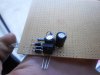
These are the markings on the poles of my ignition coil. This may be a dumb question, but which is which? Isn't the one with the green wire the ground? Thanks.
E= earth, ground
LT= low tension goes to CDI.

These are the markings on the poles of my ignition coil. This may be a dumb question, but which is which? Isn't the one with the green wire the ground? Thanks.
Answer:


Does any one know how to contact Jaguar?
FR
")
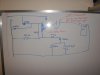
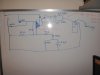
That circuit is still in the testing stages.Guestion to "Rohmel"
-Can you show how to (with a Schematic) apply the rocker on/off Switches into a RC network ?
-once you showed the Adjustable cdi of yours that had 16 different settings to choose from, and the pcb layout had those rocker Switches on it.
(hopefully this made sense as i dont know how to explain it in english)
-am i wrong or are those "Grayhill" components juts a simple on/off rocker switches ?

damn bastards want $35 to $50 for an ignition coil
i can get the circuit done today but don't want to pay that much for a coil
Try an automobile or motorcycle junk yard.
gave me the wrong packthat was the price from those places
brand new they are more like $100+ we get ripped for everything here in Aus.
I'm just setting up the circuit now.
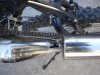
oh and on the way home from the electronic store the exhaust blow a piece of itself out.. right where the welds were to hold the rear bracket on
ah well. time to make a new one i guess.
update:
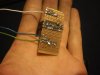
CDI is done
( non retard version) the damn guy @ the electronic store didn't give me a 47ohm resistor
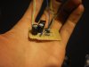
see pics
next step > find myself an ignition coil and test this unit out. If it works i make one with retard as well as better caps I non polarized ones. what type do you guys reccomend ?
The capacitors that are shown in the photo are no good for use in this application. They should be rated at least 400 volts and be a non-electrolytic type of capacitor.
Can you post pics of both sides of your PCB, so that I can look and see how it looks?Mine isn't working. Maybe I'm hooking it up wrong. I hooked blue to blue (red from my cdi) and black to black, then green to the LT on the coil. I grounded the other terminal from the coil and nothing. I bypassed the killswitch just to see if it works, and nothing. Hmm... I'll try again tonight.