happycheapskate
New Member
This is branching off of another thread about home-made wooden rollers for friction drive Dax/staton and home-made kits.
I have not built one of these but I expect one could be made very easily from an existing Dax/Staton friction kit, by adding extension straps/brackets to the channel, to move it farther from the seat tube, and cutting the stock quick-release straps shorter as needed. The new "drive roller" will be mounted between the straps like a conventional hub mounts in dropouts. The axle could even be mounted between simple drilled holes There is a method to my madness, read ahead!
Today, 06:04 PM
happycheapskate
Motorized Bicycle Elite Member
Join Date: Nov 2009
Location: Far Worse TX
Posts: 764
Re: Cheap and Easy Drive Roller
I have a design to beat all for friction drive lovers. Starting a new thread for anyone who wants to build one and report back!
This will probably sound crazy but I expect it would work very well, and eliminate a lot of guess work, and OWN all the hills.
5-9 speed derailleur shifted roller drive with " 1 inch " roller, any grit you want.
Imagine a Dax type engine channel, but about 2x as long, with the drive roller about the center, or closer to the bike seat tube. The motor will be at the end, and angled so it is about 1 inch to 1 foot above the wheel centerline. This will much lower the center of gravity and make parking easier.
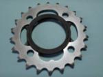
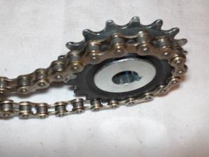
Now the dax type engine and shaft will drive a fixed, toothed cog, which pulls a chain going around a 7 speed generic bicycle hub with 7 speed (or 8 or 9, yes, 9 speed freewheels exist! ) freewheel , and using the non-laced hub as a drive roller! (epoxy and sand, or other surfacing will provide the friction for propulsion). Now with an 11-23, 12-26, or even 14-34 tooth (common sizes) freewheel, you could have a HUGE speed range including both massive underdrive and as much overdrive as your engine can handle!
For the drive channel, instead of very expensive extrusion, I would suggest welding a lighter thickness of steel plates (3 long pieces for example) together to make the "U", and bracing the sides together with long bolts and tubular spacers (like the engines sit on for clutch spacing). This should be very strong and not too heavy, esp since any flex will be taken up by the chain, and shorter "straps" for the QR skewer side will equate more strength/flex resistance. Let me know what you think in my new thread here:
Quote:
Originally Posted by cannonball2
That is a point to ponder, how to shift it with out getting extreme on the engineering. Maybe a slotted engine mount with a heavy spring to hold it in "hi". A shift lever to pull it down to "low". Probably mounted to the top tube with a gate. Once you get rolling good shift to hi and the spring pulls the engine/hi roller over to engage the tire. You would still need the lift clutch to do so. UNLESS the roller is a cone, which is a vari drive and would shift with out having to lift it. A shifter with a good friction lock would offer infinate positions.
I have not built one of these but I expect one could be made very easily from an existing Dax/Staton friction kit, by adding extension straps/brackets to the channel, to move it farther from the seat tube, and cutting the stock quick-release straps shorter as needed. The new "drive roller" will be mounted between the straps like a conventional hub mounts in dropouts. The axle could even be mounted between simple drilled holes There is a method to my madness, read ahead!

Today, 06:04 PM
happycheapskate
Motorized Bicycle Elite Member
Join Date: Nov 2009
Location: Far Worse TX
Posts: 764
Re: Cheap and Easy Drive Roller
I have a design to beat all for friction drive lovers. Starting a new thread for anyone who wants to build one and report back!
This will probably sound crazy but I expect it would work very well, and eliminate a lot of guess work, and OWN all the hills.
5-9 speed derailleur shifted roller drive with " 1 inch " roller, any grit you want.
Imagine a Dax type engine channel, but about 2x as long, with the drive roller about the center, or closer to the bike seat tube. The motor will be at the end, and angled so it is about 1 inch to 1 foot above the wheel centerline. This will much lower the center of gravity and make parking easier.
Now the dax type engine and shaft will drive a fixed, toothed cog, which pulls a chain going around a 7 speed generic bicycle hub with 7 speed (or 8 or 9, yes, 9 speed freewheels exist! ) freewheel , and using the non-laced hub as a drive roller! (epoxy and sand, or other surfacing will provide the friction for propulsion). Now with an 11-23, 12-26, or even 14-34 tooth (common sizes) freewheel, you could have a HUGE speed range including both massive underdrive and as much overdrive as your engine can handle!
For the drive channel, instead of very expensive extrusion, I would suggest welding a lighter thickness of steel plates (3 long pieces for example) together to make the "U", and bracing the sides together with long bolts and tubular spacers (like the engines sit on for clutch spacing). This should be very strong and not too heavy, esp since any flex will be taken up by the chain, and shorter "straps" for the QR skewer side will equate more strength/flex resistance. Let me know what you think in my new thread here:
Quote:
Originally Posted by cannonball2
That is a point to ponder, how to shift it with out getting extreme on the engineering. Maybe a slotted engine mount with a heavy spring to hold it in "hi". A shift lever to pull it down to "low". Probably mounted to the top tube with a gate. Once you get rolling good shift to hi and the spring pulls the engine/hi roller over to engage the tire. You would still need the lift clutch to do so. UNLESS the roller is a cone, which is a vari drive and would shift with out having to lift it. A shifter with a good friction lock would offer infinate positions.
Last edited:


