You are using an out of date browser. It may not display this or other websites correctly.
You should upgrade or use an alternative browser.
You should upgrade or use an alternative browser.
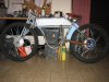
tonchio tronfio board track racer
- Thread starter ducaroso
- Start date
silverbear
The Boy Who Never Grew Up
do you have any idea who has build this bike ? cant describe how beautiful it is
No idea, but I agree it is a beautiful machine. Don't know how I missed this thread... I'm signing on for the ride. Carry on, sir!
SB

Fitting new tubs together would take a lot of time,i would try and cut it first unless you would rather do some changes other then what what you have. Then build new. But sure wouldn't take that long to cut slip in some smaller stock then weld it back together...........Curt
wret
Active Member
Please don't take offense but there are several things about your bike that are worrying. Some of them you may know about and have planned to take care of later but in the interest of safety I'll bring them to your attention:
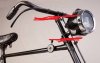
The girder fork you are using should have parallel links, otherwise they will bind and not work properly.
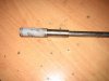
Frame splices should be "slugged" to assure that the spice is as strong as the original frame member.
The reused front fork that you are using for the rear chain stays doesn't have have much room at the dropout for axle/chain adjustment.
If you cut your frame and fork to make it lower, none of the tubes will line up. Realigning them would be extremely difficult.
The girder fork you are using should have parallel links, otherwise they will bind and not work properly.
Frame splices should be "slugged" to assure that the spice is as strong as the original frame member.
The reused front fork that you are using for the rear chain stays doesn't have have much room at the dropout for axle/chain adjustment.
If you cut your frame and fork to make it lower, none of the tubes will line up. Realigning them would be extremely difficult.
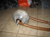
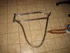
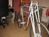
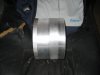
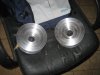
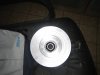
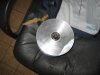
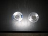
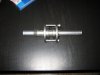
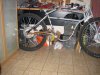
no offence at all wret after all I asked from more experts what to do the question is modify the existing or make a new frame as for your suggestions this is the handle bar that I will use which has 10cm axle above the neck which brings the links parallel but also10cm higher and in the second foto all tubes are reinforced this way inside them so everything remains straight and strong as for the rear the tube for the shaft and pedals will be shortend and an eccentric will be used for the chain.
Attachments
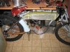
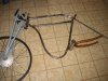
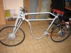
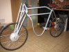
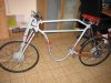
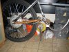
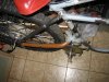
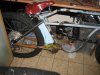
so I shortened everything its comfortable but as a result it doesn't please me the loop seems to high and short and I should definitely modify the front seat spring but the thing that bugs me most is the pedal shaft
Attachments
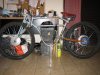
Maybe shortend the drop loop to much? I think you should turn the fork around the other way so the truss is out front,and maybe the pivet arms should be parallel so it moves freely, they might bind the way you have them. Maybe just move the crank boss down ................Curt
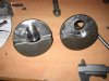
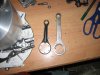
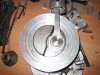
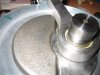
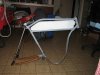
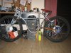
yesterday I got so happy that I received my connecting rods but as always happens when you custom build an engine the connecting rod doesn't have clearance to the crank shaft balancer and I cant machine that part because it will loose its balance so I will get a new crankshaft built a longer pin and machine the crankcase I was so disturbed that I built a moke up from fiber glas for tank cause I cant see it standing this way for so long