testing a magneto?

GoldenMotor.com

txlixard469

New Member
Feb 21, 2011
72
1
0
austin
if the white wire was taped up or as mine is taped to the frame would it matter cuz mine as well was running and now i dont get no spark but done wut everyone suggested in here as well as bought a new mag and spark oh and cdi caseand still no spark
 

txlixard469

New Member
Feb 21, 2011
72
1
0
austin
I found out today the white wire on my coil was proventing my bike from getting any spark . I switched my black wire goin to the coilw/the white wire and it started rite up , after i bought a whole new engine at least now I got 2 engines and more knowledge
 

Spaz_Static

New Member
Jul 24, 2011
80
0
0
North Carolina, USA
If you have an ohm meter, your dad will know how to use it, try this:

Use Low Ohm-Meter Scale About 200 Ohms

Magneto Coil

1) Check Ohms between BLACK wire and WHITE wire. Reading should be around 2 Ohms{getting slightly less than infinite}
2) Check ohms between BLUE wire and WHITE wire. Should be around 300-400 ohms. {Getting right at 400}

CDI

Use Ohm Meter High Scale About 200-K
1) Positive lead on BLUE wire and Negative lead on BLACK wire should read infinite (no activity) {reading about 4400 ohms}
2) Positive lead on BLACK wire and Negative lead on BLUE wire. Should be about 130-150 K-ohms {getting infinite}
3) Positive lead on Spark Plug wire and negative lead on BLUE wire. Should read between 135-155 K-ohms {reading infinite}

Switch to Low Scale 20K
4) Measure between Spark Plug wire and Black lead. Should be about 2.5 - 2.7 K- ohms { reads about 8000 ohms}

As for keeping water/dirt out. Make sure the gasket is good or seal it with a small bead of silicone and fill the hole where the wires exit the case with the same silicone sealer.

Tom
My ohm meter has one setting, 1k ohms (rest are dcv, acv, and dc mA). My readings are added to 2Door's post quote in curly brackets, and some vary wildly from what they are supposed to be.

I also wanted to say that if I connect my white wire to the black wire off my mag (as well as blue to blue), I get spark, but its weak.
 

Spaz_Static

New Member
Jul 24, 2011
80
0
0
North Carolina, USA
Father also thought it would be worth mentioning that he doesn't know if that meter is worth a hoot anymore. As for continuity, yeah, should be fine, but hit or miss on anything else. The meter is older than I am. I'm 22. Haha
 

Spaz_Static

New Member
Jul 24, 2011
80
0
0
North Carolina, USA
Put on my new NGK plug and it seems to be running a bit better. Stil seems a little off though.... I might have to break and spend an extra twenty on a new mag and or CDI.
 

GearNut

Active Member
Aug 19, 2009
5,104
11
38
San Diego, Kaliforgnia
Spaz, have you tried re-soldering the soldered ground connection on the mag, both where the black wire attaches as well as the center common ground between the 2 windings on the coil? Both connections are notorious for being "cold soldered" at the factory. This provides a poor electrical connection that will progressively get worse and then completely fail over time. A cold soldered connection appears fine just by looking at it, but has a high resistance to electricity flowing through it which reduces the overall power output signal going to the CDI box which results in a weak spark.
 

Spaz_Static

New Member
Jul 24, 2011
80
0
0
North Carolina, USA
I have not tried that. The ground (black) wire is bolted to the mag and not soldered, and I don't know where the common ground solder point is located.

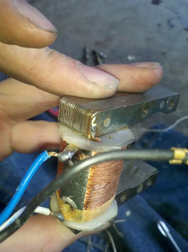
I've stripped off the coating stuff and looked, and I'm not really sure where the common ground is... is it the little solder spot on the top of the mag in this picture (the focus/center of the pic)?


Well, I'm guess it was, or at least that it was the problem. I resoldered it and my bike runs fine (so far). I did wrap the coil with electrical tape... hopefully it either isn't needed, or does a satisfactory job.
 
Last edited:

GearNut

Active Member
Aug 19, 2009
5,104
11
38
San Diego, Kaliforgnia
Yup, you found it! That is the common center ground in your photo. It is the cause of many failed mags. So simple to repair yet many, many mags have been thrown away because of it. The other common cause is the eyelet that the factory crimps onto the end of the black wire (with the mounting bolt through it), that you also found. The wire should have been soldered to the eyelet after crimping (some are, some are not), and on some installations the lacquer that they coat the mag with acts like an insulator between the eyelet and the metal of the mounting bolt and mag frame. They seem to coat everything on the mag with lacquer before assembly, even the parts that they should not.
 
Last edited:

Spaz_Static

New Member
Jul 24, 2011
80
0
0
North Carolina, USA
Yeah, I noticed that. Kind of annoying, really. I have a question; how did that solder joint come to fail? It was working fine one day, and then was crap the next. It still seemed like it was firmly attached, like it hadn't come loose or anything...
 

GearNut

Active Member
Aug 19, 2009
5,104
11
38
San Diego, Kaliforgnia
Now you opened a can of worms!
It failed due to being cold soldered at the factory. This is most commonly caused by melting the solder onto the connection. Sorta like painting it on with a hot blob of molten metal rather than properly flowing it into the connection.
A cold soldered connection can easily appear to be good and hold the wire(s) firmly. What is happening on the inside of the connection is a whole 'nother story though.
A properly soldered electrical connection can only happen when all parts involved are just hot enough to melt the solder and a cleaning flux has been used. The part(s) need to be clean, free of corrosion and oxidation and at the correct temperature. This allows an electro-mechanical bond to occur. If one or more of the parts are corroded or not hot enough you end up with only a mechanical bond. This bond may still pass electricity through it, but do it poorly with high resistance.
Corrosion is the cause of many soldered failures. Most soft electrical solder has within the "wire" a rosin or water based cleaning agent inside it, like the filling in a Twinkie. This needs appropriate heat to work and clean the parts properly.
A part that is too cold will not get cleaned properly by the cleaning agent.
Inside a cold soldered joint, on the surface (at the molecular level) of the part(s) you will typically find corrosion between the part(s) and the solder. This is a double whammy as there is a poor/ no electrical bond between the solder as well as corrosion, both of which act as resistance to electrical flow. Electricity by nature can accelerate the action of corrosion by electrolysis. It will nurture it and make it grow. The resistance in the connection will also create heat as the electricity tries to pass through. Heat also accelerates the growth of corrosion. This turns into a self feeding, recycling problem.
Electrical flow and more heat creates more corrosion which in turn creates more heat. The cycle continues until the resistance gets so high that the connection can no longer pass electricity through it.
One last note, Did you notice that above I stated that the part(s) need to be just hot enough to melt the solder. Get the parts too hot and the solder will still melt, but corrosion/ oxidation will occur due to the excessive heat involved and the connection will have nearly identical problems as a cold soldered connection. No cleaning agent can keep the part(s) clean of oxidation if excessive heat is applied.
 
Last edited:

Henshooter

New Member
Feb 10, 2014
275
0
0
Melbourne au
If you have an ohm meter, your dad will know how to use it, try this:

Use Low Ohm-Meter Scale About 200 Ohms

Magneto Coil

1) Check Ohms between BLACK wire and WHITE wire. Reading should be around 2 Ohms
2) Check ohms between BLUE wire and WHITE wire. Should be around 300-400 ohms.

CDI

Use Ohm Meter High Scale About 200-K
1) Positive lead on BLUE wire and Negative lead on BLACK wire should read infinite (no activity)
2) Positive lead on BLACK wire and Negative lead on BLUE wire. Should be about 130-150 K-ohms
3) Positive lead on Spark Plug wire and negative lead on BLUE wire. Should read between 135-155 K-ohms

Switch to Low Scale 20K
4) Measure between Spark Plug wire and Black lead. Should be about 2.5 - 2.7 K- ohms

As for keeping water/dirt out. Make sure the gasket is good or seal it with a small bead of silicone and fill the hole where the wires exit the case with the same silicone sealer.

Tom
Ok so it looks as if I've fried yet another coil ,I did as suggested in the post to test the CDI ,now it switch to 200k nothing at all ,switch back to 2000 setting and get 754

I place negative to spark lead and positive to black and get 10.8 on 200k setting , I'm lost
 

Martin1963

New Member
Jan 23, 2015
3
0
1
Phoenix
Thanks for that info but I'm trying to test the Huffy Davidson ignition coil because I'm building my own hi performance cdi circuit that is used with the seperate ignition coil I bought and that is what I'm trying to test. I hope someone can help me with the resistance measurements for that coil.
 

MEASURE TWICE

Well-Known Member
Jul 13, 2010
2,784
1,296
113
CA
http://www.autozone.com/test-scan-a...gnition-spark-tester/10257_0_0/?checkfit=true

This has an adjustment for I think distance the spark reaches. That it then correlates with the scale 0 - 40,000 volts approximate. I think also takes into account the fact that under compression spark requires higher voltage. How much difference there is between engines with different compression in the cylinder maybe it does not matter that much.

I have to find that Briggs and Stratton description of their tester it was a good article. It also mentioned I think some way to have a check for spark in addition to just the tester, but by having both the plug under compression in series with the tester. If the tester sparked, then you know the plug must have also. The idea there is two gaps would have had to sparked. That would require more than enough voltage to run the engine.

Another thing was spark color was mentioned as not being important at all. The reason is the hottest spark would produce ultra violet range humans can't see. The different colors red, blue, yellow, they mentioned has to do with things in the air like sulfur and other impurities that give off color.
 
Last edited:

MEASURE TWICE

Well-Known Member
Jul 13, 2010
2,784
1,296
113
CA
I should say the measurement does tell approximate voltage by the maximum amount of gap you adjust to and it still jumps the spark gap of the tester. There are marking in voltage where you read on the tester.

I'll try to find the Briggs article. It mentions you must have at least 250 rpm with the pull start to get the voltage required to get the starting voltage. I suspect that is why the windup starters you press a button is necessary for those (not you per say), but those who can't pull the rope fast enough.

Most the kit bikes use your pedaling the bike to start so that makes it easier I suspect. I suppose with pulg removed rear wheel off ground you could crank the pedal to see the tester work.

Others may know more on that part.

Found the website on testing from Briggs:

http://www.briggsandstratton.com/eu/en/support/faqs/ignition-system-theory-and-testing
 
Last edited: