Roll Your Own CDI

GoldenMotor.com

Are You Going to Roll Your Own CDI?


  • Total voters
    123

Drewd

New Member
Jul 25, 2008
425
0
0
Colorado
I'm comparing this image to a recently purchased Jaguar CDi (I have two other bikes and don't wish to spend another 88 bucks shipped each for next two bikes). There are 4 jumper pin on my Jag CDI but the redrawn schematic only shows 2. A1/A2 jumper on Jag CDI determine start/idle ignition timing and jumpers b1/b2 determine how much ignition retardation occurs at higher rpms. With my setups, I wonj't be using any jumpers on the A side (stock timing at idle/low speeds) but will probably need more retardation at higher rpms due to high compression head and reed valve intake. Rohmell, does your redrawn schematic just eliminate the ability to adjust base/start ignition timing?
Thanks!

PS I can send you pics of my board front and back if you like. I have an expensive cannon digital camera but for life of me can't get it to take a good picture..will try with my cheap cam phone if you like. Thanks!


Here is the original schematic, cleaned up the lines a little bit:


Here it is redrawn:
 
Last edited:

Drewd

New Member
Jul 25, 2008
425
0
0
Colorado
Pics of new Jag CDI I just purchased and received in mail today...darn cam on droid phone is better then my cannon camera.


Dax: where the heck are you guys? You've cloned a shifter kit, any reason why you can't clone this item and sell it for a reasonable price? I'd pay $40-50 for it but current price by JNM is stupid crazy.
 
Last edited:

BigBlue

Member
Nov 29, 2011
778
0
16
California
Why would Dax want to clone another man's intellectual property? Jaguar spent time, effort and money developing his product, as Duane has done developing his products. Would it be O.K. if Jaguar copied Duane's products and sold them?

Clone Jaguar's CDI and sell it? Do it yourself. Looks as if you have the intellectual capacity to do so.

You did buy Jaguar's CDI. Thanks for supporting a MB business even though you don't agree with his pricing. We have fewer and fewer MB businesses to select from. We don't need any more going out of business.

Rohmell will be coming out with a CDI product that might be cheaper or be a better product than Jaguar's - let the market decide the price - not cloning.

Good Luck,

Chris
AKA: BigBlue
 
Last edited:

Ratchetbirds

Member
Jun 12, 2011
125
1
16
Eastern Wash.
Pics of new Jag CDI I just purchased and received in mail today...darn cam on droid phone is better then my cannon camera.


Hi Drewd, Do you have a macro setting on that Cannon? There should be one, it is the flower symbol. Set it on that and try it. My cheap lil Sony takes incredible photos in macro mode. Best of luck to you.
 

Drewd

New Member
Jul 25, 2008
425
0
0
Colorado
With no malice against Dax, they already do clone other products for resale.
1. Their shifter kit is a copy of SBP's 1st generation shifter kit.
2. Their friction drive is a copy of a US manufacturer's friction drive. I belive the original designer/manufacturer went out of business but I could be wrong.
3. Their 3:1 "copy writed" gear box is easily available elsewhere


If jag wants to do the same to Dax, I'd have no problem with it provided there is no patent protection on the item. Copywrite protection does not protect against reproduction unless the copywrited plans are used to soley create the item in question. A copywrite does not prevent reproduction of an item by reverse enginering it.

Like I said earlier, I bought one from Jag and I won't buy another from him or his supplier. JNM is he only vendor I've run across here that overcharges for an item that is hand built and in my opinion poorly crafted. I've already had one lead break off a solder point from minimal manipulation. For the cost, the circuit board should be etched and the entire assembly embedded in epoxy or material similar to the stock CDI. The plans for an iginition simple already exist on the internet. Jag's CDI takes it a step further with jumper cables that alter capacitance values to advance initial and retard high rpm timing.


Why would Dax want to clone another man's intellectual property? Jaguar spent time, effort and money developing his product, as Duane has done developing his products. Would it be O.K. if Jaguar copied Duane's products and sold them?

Clone Jaguar's CDI and sell it? Do it yourself. Looks as if you have the intellectual capacity to do so.

You did buy Jaguar's CDI. Thanks for supporting a MB business even though you don't agree with his pricing. We have fewer and fewer MB businesses to select from. We don't need any more going out of business.

Rohmell will be coming out with a CDI product that might be cheaper or be a better product than Jaguar's - let the market decide the price - not cloning.

Good Luck,

Chris
AKA: BigBlue
 
Last edited:

multipaul

New Member
Mar 31, 2012
74
0
0
Germany
A specific question about the SCR. Which types can I use?
In the chematics there are always the three letters, but it is never specified.

Behind every diode the type is written, behind every resistor the value is written. But nothing behind the SCR!

Multipaul
 

Greg58

Well-Known Member
May 1, 2011
5,350
2,574
113
66
Newnan,Georgia
On page 5 is a list of parts needed, I think some have been updated but the scr is the same. I haven't built mine yet but have been keeping tabs on the progress.
SCR: 1000V 3A
 

ivan H

Member
Oct 8, 2011
622
1
16
australia
Hi Multi Paul, the scr is a C106D. Try & get an industrial rated 1. I m putting together another unit wth at least 2, maybe 3 jumpers on the initial fireing setting, 2 on timing caps & 1 on timing resistor & 1 between Kathode & Gate. I'll test for couple of weeks & if all good I'll post schematic & results. Cheers
 

ivan H

Member
Oct 8, 2011
622
1
16
australia
Ok, for those wanting the exact Jag circuit, try replacing the 27 ohm pulldown resistor with an 15 & 1 ohm in series, the 390 ohm between kathode & gate with a 470 ohm & 620 ohm in the timing R/C network with a 760 ohm. If someone could put a degreed wheel & timing light on & check the timing curve against his I think it'd pretty well in the ballpark. Cheers
 
Last edited:

ivan H

Member
Oct 8, 2011
622
1
16
australia
actually, I just looked at pic posted by Drewd, (thanx) & it shows a 390 ohm in series with 1K ohm between kathode & gate. The both 0.47uf add on caps have jumpers 2 earth for 2 retard curves. I cant make out (on phone) the value of the resistor in the upper left corner, above the 120 ohm add on resisistor that gives the 3rd initial firing point, maybe someone else can & post, but there u have it. This circuit is pretty forgiving of change, so dont hesitate to 2ailor to ur liking. Cheers
 

Professer_Dave

New Member
May 25, 2012
8
0
0
Milwaukee, Wisconsin
Hi All,

I'm new to this forum.

I've been thinking about rolling my own for a while (CDI that is ... ). I finally had time to build one over the last couple of days and thought I'd share.

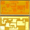
The design is basically the same as one posted earlier with a couple of minor changes to accommodate resistor values I had on hand. Series 22Ω – 5Ω at JA instead of 27Ω // 120Ω (same result though). I have access to a PCB mill, so I laid out and milled a few boards (I have a couple extras if anyone is desperate!). Schematic, layout, photos, etc., are below.

I haven't had time to fully test jumper settings yet, but overall there is a noticeable decrease in vibration along with more low RPM power and no high RPM limit where the power drops out. After a quick trial in the parking lot where I work at the University, it seemed as though both jumpers engaged gave the most power for the widest range of RPM ... more testing needed though. My ride home today was SWEET!

Hope all is well with everyone.

Peace,
Dave

P.S. - I used a 1984 Yamaha XT250 Motorcycle coil that I purchased new off of EBAY. The primary measured well under 1Ω (about 0.2Ω) which others have indicated is no good? For the record, this one seems pretty HOT for such a low resistance ... works GREAT!

P.S.S. More about me if anyone cares ... https://pantherfile.uwm.edu/davidm/www/
 

Attachments

Last edited:

ivan H

Member
Oct 8, 2011
622
1
16
australia
Hi Dave, neat job. I've just used pre drilled prototype board with the copper foil strips vertically, & dremelled off unwanted strips & laid out like the photos of Jags. It does smooth it out & let rev higher. Put lota miles on, no prob. Just started another with 1.39k between kathode & gate, 16 ohm pulldown with 120 & 220 ohm in parlell on jumpers & 760 ohm in R/C timing network. Cheers
 

ivan H

Member
Oct 8, 2011
622
1
16
australia
The coil I've been using (out of mates shed who likes bikes in the 4 or 5 hundred cc range) also had very low primary resistance, I cant exactly remeber wot. It produces a hot enough spark, I've never had problems tho I think a smaller 1 would b even better due to limitted current from 1uf charge cap needed due to stator limitations. All in all its a big improvement over the stock cdi & is pretty forgiving of chnges to the circuitry. Cheers
 

ivan H

Member
Oct 8, 2011
622
1
16
australia
Tip, test for jumper position in kathode circuit under low rpm load, jumper in timing network on flat where u can wind it out. Which ever gives best rpm/speed for both. Have fun, cheers
 

Professer_Dave

New Member
May 25, 2012
8
0
0
Milwaukee, Wisconsin
ivan,

Thanks for the tips. I'm quickly realizing that looking for the perfect timing curve is a bit like searching for the Holy Grail ... the quest may never end! I'm already thinking about a digital/microcontroller based version with an adjustable, table based, lookup for advance/retard. I guess that's half the fun.

50% of the fun is riding ... the other 50% is dreaming about 'pimping' your ride (smoother, more power, more speed, more efficiency, more, more, more ...)

Also, I noticed that it was on Jag's original "Repairing the KDX CDI" page that he was trash-talking the low resistance primary winding. I doubt dc primary resistance is any issue at all since the IR drop will be small compared to the ~300V 'spike'. The current delivered to the primary should be fairly independent of its dc resistance. I suspect coil inductance is likely what limits the initial current (at least until the spark gap breaks down), and when the cap is discharged, the 'catch' diode keeps the current flowing for a bit? I simulated this in Spice a while back ... I guess I should take another look. Anyone know what typical inductance we are dealing with?

Best,
Dave
 
Last edited:

ivan H

Member
Oct 8, 2011
622
1
16
australia
i havent really thought about it, tho its sounds like u have the knowhow 2 develop it good bit futher. Electronics isnt even a hobby of mine, working on this came out of nescessaty, just like all I do know bout electronics came from playing electric guitars thru valve (tube) amps for years, & due 2 location, getting repairs or modifications done was a matter of searching & then large cost so I decided to learn as much as I could about & ended up getting employment from. My very limited solid state knowledge was a bi probuct. Cheers
 
Last edited:

Greg58

Well-Known Member
May 1, 2011
5,350
2,574
113
66
Newnan,Georgia
Sounds like you guys have this thing figured out, I have been following this thread with interest but have never built anything on this scale. If and when I start one I may have to lean on you guys a lot! Greg.
 

ivan H

Member
Oct 8, 2011
622
1
16
australia
Hi Greg58,,, no problem. Its only a few bucks in components, all of which r readily available at any electronics outlet, & a couple of hours max putting it together, & it will put a smile on ur face when u take ur bike for a spin with it on for the first time. If u dont understand nything at all, just ask rather than let it hold u up,,, u'll hve it up & running in no time. Cheers