My 1st build - CB2 inspired rack mounted, scissor lift, FD

GoldenMotor.com

OC_Hugh

Member
Jul 18, 2017
40
2
8
NE Washington
Hello everyone.

This will be my first motorized bicycle project. It will combine features found in a couple of builds done by Cannonball2 a long time ago.

The plan is a scissor lift mount with a little HF engine centered over the rear wheel. I like the simplicity of CB's off-set FD scissor lift and I really like his centered version with the centrifugal clutch and jackshafted FD roller. My reason for combining ideas is that I feel the need to be able to shut off the engine while pedaling or coasting and be able to bump start it when approaching a hill. This combo should provide that.

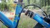
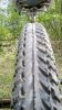
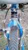
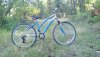
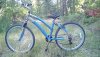
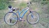
Anyway, that's my plan and here's what I'm working with.
Hugh
 

Attachments

Last edited:

OC_Hugh

Member
Jul 18, 2017
40
2
8
NE Washington
I plan to use this as an occasional commuter bike. My route to work is about 6 miles. Half the route is packed dirt or fairly well maintained gravel, the other half is a lightly used well maintained paved road. It's okay to use ATVs, etc on the paved roads as long as the are legal. I'll deal with the legalities right after I've built it.

The route is mostly down hill with a few uphills. The route back is the one I struggle with being uphill and typically at the end of a long day in the afternoon heat.

This should be fun.
 

cannonball2

Well-Known Member
Oct 28, 2010
3,682
221
63
Colonial Coast USA.
Looks like a nice bike, a full suspension is the way to go. Some thoughts.

Not having hands on the bike I cant tell if there is room below the shock for a clamp type mount. If not how will the mount attach? The mount must be completely on the rear triangle. IE cant be anchored to the seat post, if the suspension is to have travel. It looks like the bike is of the soft tail design with very little travel?

Also tires are very important. I tried many types and fount the best to be the common 2.125 flat top cruiser
tire. It offers the most roller contact with out excessively low tire pressures(around 30psi). I like the newer
Hookworm style tire and it seemed to work well with the last FD I did with the small Echo trimmer engine running a knurled BMX peg( small rollers are hard to get to grip). Just be sure the frame will allow larger
tires than what the bike appears to have(1.95s maybe?).

If running a reduction run the largest roller you can fit. I have run close to 4", the bigger the better. I have run wooden rollers pinned to a 5/8 jack shaft. Oak wears like iron and is very tire friendly. sand and gravel roads
have very little wear effect on it. Common 2x4s will make workable rollers especially to experiment with
sizing. I laminated 3/4 oak boards to get my rollers(right on the engines shaft!). A roller generally doesnt need to be much wider than 1.5" as thats about all the tire contact patch is.

Not trying to tell you what you should do, letting one build from their ideas is where innovations
come from. Just offering some of my experiences with FDs. Properly done ,they are worth the effort despite
the negativity that usually surround the topic. Nothing is smoother or quieter except an Ebike, another
of my favorite MBs!
 
  • Like
Reactions: OC_Hugh

curtisfox

Well-Known Member
Dec 29, 2008
6,046
3,948
113
minesota
Had one of them bikes for my wife, very short shock travel. But if all the weight is put on the rear wheel or above it may do ok. I started on full suspension build, and what i did was take rear triangle tubes and welded them to the existing triangle, with a plate on top. Sorta like putting the bottom bracket straight up, and replaced with a plate, making a second triangle. But that wont work for scissor lift. ..........Curt
 
  • Like
Reactions: OC_Hugh

OC_Hugh

Member
Jul 18, 2017
40
2
8
NE Washington
Hey CB,
The tires are 26 x 2.0 and the tread surface is quite flat with a concave area in the center.

The rear travel is only about 5/8" and the label on the spring says 300#/in. There is very limited room for mounts, about 1/2" below the seat clamp and a couple of 7/8" spaces further down the frame. There is actually an 1" available if the upper clamp mount also acted as the seat post clamp.
Hugh
 

Attachments

Last edited:

curtisfox

Well-Known Member
Dec 29, 2008
6,046
3,948
113
minesota
The engine has to move with the rear triangle, so can't be mounted to seat post. It will have to mount to the rear triangle, to keep constant pressure on the tire................Curt
 
  • Like
Reactions: OC_Hugh

OC_Hugh

Member
Jul 18, 2017
40
2
8
NE Washington
Hi Curtis, thanks for helping me understand that. Maybe I'll just replace the rear spring assembly with a bar and forgo a rear suspension. That should simplify the build.
 

OC_Hugh

Member
Jul 18, 2017
40
2
8
NE Washington
Is there a preferred location for the roller? It seems like centered under the motor would improve roller contact but obviously raises the cg. On my bike there is room forward of the motor but that places it very near to the rear caliper. Would that be a problem? I think that a forward position would have less lift than a rear position since the pivot point is in the front. That might not matter since it only needs to be lifted a little bit.
 

cannonball2

Well-Known Member
Oct 28, 2010
3,682
221
63
Colonial Coast USA.
Foward on the roller is good. If the mount pivots from the seat post with the engine to the rear that will give a good moment
arm to load the roller with the engines weight. Less spring
pressure needed. If your tire runs true you will only need about an 1\8" of lift.
 
  • Like
Reactions: OC_Hugh

OC_Hugh

Member
Jul 18, 2017
40
2
8
NE Washington
Thank you CB. I'd like to keep the motor as close to centered over the rear axle as possible. Putting the roller in front of it should also help the bike be more balanced.
 

OC_Hugh

Member
Jul 18, 2017
40
2
8
NE Washington
In another discussion CB said, "If running a reduction run the largest roller you can fit. I have run close to 4", the bigger the better"

Is that because a larger roller has more contact with the tire and is less likely to slip?

I'm in the process of determining what drive components I'll need. In your HF 2.5 FD thread you wrote this, "Climbs huge hills like a mountain goat. I am slightly underdriven with a 3.25/3.5 pulley combo. I have a 3" pully comming to try which will slightly overdrive it. Its designed so the belt works with either pulley. Top speed calcs. to 28+mph with a 2" roller@ 4800rpm."

The largest hole saw I have is 3.5". I expect that will create a 3.25" roller. Since for now I'll be using a 10 tooth cent clutch what size sprocket do I need on the roller to duplicate your results?
 

OC_Hugh

Member
Jul 18, 2017
40
2
8
NE Washington
I realize I won't be able to bump start with the centrifugal clutch but it looks like my first version will have to be set up that way. The second version will have the scissor lift and belt drive.
 

cannonball2

Well-Known Member
Oct 28, 2010
3,682
221
63
Colonial Coast USA.
I had a great speed calc that I lost when my old computer died. It would determine roller sizes/speeds. Generally a larger slower turning roller is better than a smaller faster one. On larger engines the minimum I usually ran(direct) was 2"(think I had might have a 1.8 for trailer towing).

With the engine centered I doubt there will be clearance for a larger roller. A 2-2.25" roller will work fine especially with a centrifugal clutch as the take off more gradual.

What speeds do you want to run? If hills are a factor then opt for a lower ratio. Its much easier to
set up for easy roller changes than reduction ratio changes. If you can work this feature in then
a 1:1 drive would be fine. This would require some adjustment of the engines "rack" to allow the different size rollers. 1/4" makes a great difference in speed.. Make the engines rack adjustable
up/down and the different roller sizes can be adjusted for. Build the engine mount/rack first to see just where the roller will position. If you make the rack wide enough then a larger roller could be accommodated by being able to protrude thru the rack.

I strongly recommend roller changeability.i
Then new rollers/speeds are as close as the next size hole saw.

I assume you saw the Maytag build with the three speed roller?
 
Last edited:
  • Like
Reactions: OC_Hugh

OC_Hugh

Member
Jul 18, 2017
40
2
8
NE Washington
According to this chart your 2" roller (at 4800 rpm and a 3.25/3.5 pulley combo at 28mph) was spinning at aprox 33,000 inches per minute. If that is the rotational speed for about 30mph the I can calculate the drive ratios with larger rollers. This chart only has data for 2" , 2.5" and 3".

roller_size_speed_comparison.jpg
 
Last edited:

OC_Hugh

Member
Jul 18, 2017
40
2
8
NE Washington
Hills? Short answer,yes.

This is what my route from work to home looks like according to Google Earth. And that uphill portion is typically in full sun. Plus there are so many nearby trails and logging roads I'd like to explore. Top speed is less important to me than being able to safely navigate gravel roads and dirt trails.
Screenshot_2017-07-22-17-00-20_kindlephoto-673376495.jpg
 

OC_Hugh

Member
Jul 18, 2017
40
2
8
NE Washington
And yes, easily swappable rollers seems like the way to go. I'm also thinking that staying with a centrifugal clutch setup would be better for low speed operation since it can slip when needed. I'm not a motorcycle guy at all. That only time I rode any sort of cycle was a Trail 90 over 20 years ago. I'm comfortable on bicycles though.