
You are using an out of date browser. It may not display this or other websites correctly.
You should upgrade or use an alternative browser.
You should upgrade or use an alternative browser.
My 1st build - CB2 inspired rack mounted, scissor lift, FD
- Thread starter OC_Hugh
- Start date
OC_Hugh
Member
I found another helpful CB2 build. His bolt together mount should work fine on the rear of my bike.
https://motorbicycling.com/threads/lifan-genesis-mtb-its-all-lowracers-fault.30556/
https://motorbicycling.com/threads/lifan-genesis-mtb-its-all-lowracers-fault.30556/
cannonball2
Well-Known Member
That was a pretty awesome bike!
I did some number crunching with a calculator and came up with this. The # of inches in a mile is
63300. This is equivalent to 60mph if traveled in an hour. Divide this by 60 and you get the inches for 1mph(1056). Multiply this by a given mph, say 18 and you get the inches of roller needed for that speed/distance(19008). Multiply your roller by 3.14 then divide that into the mph/in figure. 2in roller has a circumference of 6.28in. 19008 divided by 6.28=3026. You will have to turn a 2" roller 3026 rpms to go 18mph. I think.
To make sort of quick replaceable rollers, run a 5/8 jackshaft. You can simply remove the off side drive bearings lock collar pull the shaft over a bit and drop the roller out. The roller can be held in place by two lock collars(set screw type). Drill the shaft slightly to make a deep dimple for the collar sets to bottom in. That makes a positive lock on the shaft. Cross drill and tap one collar to 1/4-20 and make a drive pin that threads into the collar from a bolt. Just drill corresponding holes in the rollers then lock in place with the collar. You will be hindered a bit by having a chain to contend with as it will have to be removed to slide the shaft.
I had a spring loaded idler for the belt that tolerated moving the shaft with the belt in place.
However a chain will run with a well designed spring idler also. Simply stack a couple of
sealed bearings to make the wheel and leave enough chain on the non drive side run to just be able to lift the chain off.
The beauty of the direct drive bikes is a roller change could be made in a minute or less.
Last edited:
cannonball2
Well-Known Member
Back to my calculator, my math doesn't jive
with your chart I just saw.
with your chart I just saw.
cannonball2
Well-Known Member
OK, I find the chart initially confusing. I read it wrong. My math is correct
The easiest way to calc the rpm of a roller is to use the magic# 1056.
Multiply this times the mph desired then divide by the circumference of the roller.
I will do the 17.8@3000 rpm on the chart.
1056x17.8=187968. 187968 divided by 6.28(2"roller)=2993rpm. Im guessing they rounded
the value.
Conversely to figure mph multiply the circumference by the rpm then divide by the magic# 1056.
3000x6.28=18840 18840 divided by 1056=17.84
Now one can easily figure roller performance. It is unique among all drive ratio/speed
calculations.
OC_Hugh
Member
OK, I find the chart initially confusing. I read it wrong. My math is correct
The easiest way to calc the rpm of a roller is to use the magic# 1056.
Multiply this times the mph desired then divide by the circumference of the roller.
I will do the 17.8@3000 rpm on the chart.
1056x17.8=187968. 187968 divided by 6.28(2"roller)=2993rpm. Im guessing they rounded
the value.
Conversely to figure mph multiply the circumference by the rpm then divide by the magic# 1056.
3000x6.28=18840 18840 divided by 1056=17.84
Now one can easily figure roller performance. It is unique among all drive ratio/speed
calculations.
Thank you CB, that is very helpful information.
OC_Hugh
Member
I have another question. You said, "I had a spring loaded idler for the belt that tolerated moving the shaft with the belt in place. However a chain will run with a well designed spring idler also. Simply stack a couple of sealed bearings to make the wheel and leave enough chain on the non drive side run to just be able to lift the chain off."
I've seen photos of your spring loaded idler but I'm having trouble visualizing how the stacked bearings you describe will support a chain.
I've seen photos of your spring loaded idler but I'm having trouble visualizing how the stacked bearings you describe will support a chain.
cannonball2
Well-Known Member
The bearings are stacked together side by side then thru bolted to a spring loaded arm of course. Chain runs very happily on the smooth bearing shells. Or you can run
the common MB kit idler wheel. A smooth idler wheel
allows for chain run out and is less critical than running
a tooth idler.
the common MB kit idler wheel. A smooth idler wheel
allows for chain run out and is less critical than running
a tooth idler.
cannonball2
Well-Known Member
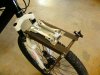
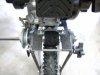
Heres a pic of two flange bearings back to back making a belt idler(works on chain too)
on my Maytag 3speed FD. A very complicated build!
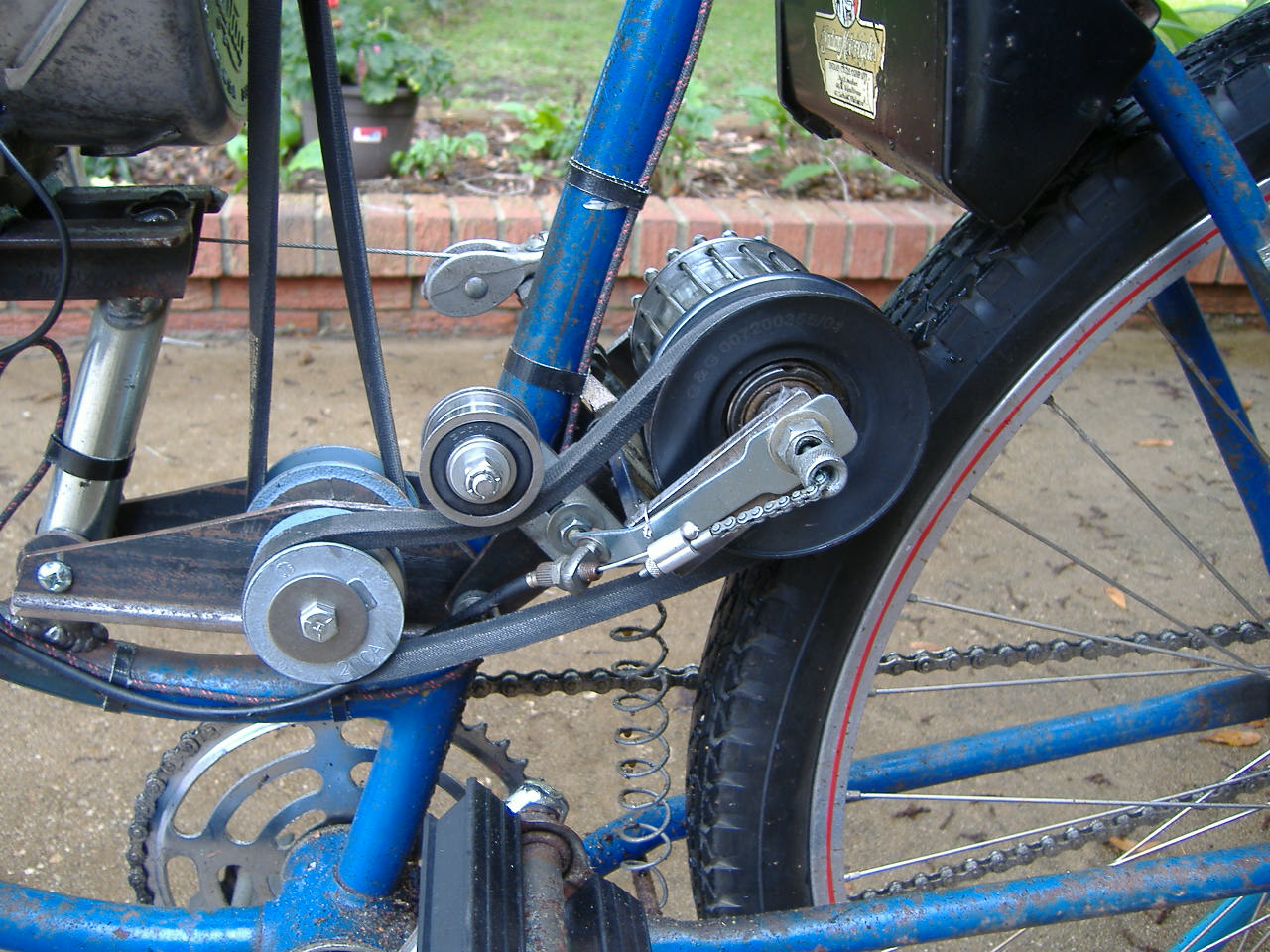
on my Maytag 3speed FD. A very complicated build!
cannonball2
Well-Known Member
MEASURE TWICE
Well-Known Member
I was wondering what the engine setup is like and mounting. You have pictures? That roller for a moment looked like one of the pie electric motors. It grabs well on the wheel I guess.
cannonball2
Well-Known Member
Hey MT
Not wanting to hack OC Hughs thread I will post a link to the build here for you. Its all explained
there. I will say the spokey dokey drive is positive displacement and not friction as it might appear. No slippage wet or dry.
https://motorbicycling.com/threads/more-maytag-mayhem.57197/
Not wanting to hack OC Hughs thread I will post a link to the build here for you. Its all explained
there. I will say the spokey dokey drive is positive displacement and not friction as it might appear. No slippage wet or dry.
https://motorbicycling.com/threads/more-maytag-mayhem.57197/
OC_Hugh
Member
This might be helpful for those of us that are math challenged.
http://www3.telus.net/findnchoose/sprocket_calculator.html
http://www3.telus.net/findnchoose/sprocket_calculator.html
cannonball2
Well-Known Member
No FD inputs that I saw. Great for chain\sprocket calcs.
OC_Hugh
Member
Noted. I was looking for simple way to calculate how input rpm and output rpm change when plugging in a variety of sprocket sizes. I think it will make it easier when I'm figuring out my drive ratio.No FD inputs that I saw. Great for chain\sprocket calcs.
OC_Hugh
Member
This is what I came up with. Revisions due to math mistakes or an error in my logic are certainly possible. My biggest assumption is that my 3 1/2" hole saw will make a 3 1/4" roller. I'll do a test cut tomorrow.
Goals
30 mph @ 4800 rpm
Good hill climbing ability
Known Factors
My clutch has a 10 Tooth Sprocket
I own a 3.5" hole saw (3.25" roller?)
Calculated Factors
3.25" roller needs to spin at 3102 rpm to go 30 mph
10T to 15T sprocket will spin the roller at 3200 rpm
10T to 16T sprocket will spin the roller at 3000 rpm
4" roller with a 15T sprocket = 38 mph
4" roller with a 16T sprocket = 35.7 mph
2" roller with a 15T sprocket = 19 mph
2" roller with a 16T sprocket = 17.9 mph
cannonball2
Well-Known Member
Writing from memory(may be questionable) as I recall the Red Schwinn bike ultimately
ran a roller direct some where in the 3.5"+ range around 4500rpm. The bike topped around 45 mph, easily out running my friends smaller engined vintage Vespa, much to his dismay.
Thing was I had to pedal pretty fast before dumping the "clutch". The engine lugged a bit up to
around 15-18 mph then began to take off.
The Mongoose ran governed which was cool. It was a great form of cruise control. I used a friction lock thumb throttle and it was a set and forget. It handled the cruise speed and poured it to it on the hills. This worked well only because this bike cruised the back country. It cruised around 25 mph @3600 with a 2.3 roller(cut with a 2,5" saw), and climbed fairly well. If I was really in hill country I swapped to a roller closer to 2".
I only said the above to give an idea of extremes that can be done with roller sizes.
Your target speed/gearing sounds feasible. 30 mph is a nice speed, will keep up with a lot
of urban traffic(in my town anyway). 20-25 is a nice cruise. It would be nicer if the engine rpms
are in the mid 3k range.
Go for it and see how it works out. May take a roller adjustment one way or the other. If you get serious about FDs with wood rollers you will soon have quite an assortment of hole saws!