Magneto rewinding

GoldenMotor.com

reg454

New Member
Jan 11, 2009
269
0
0
42
michigan
Jim what I believe what is wrong is the gauge of wire I used for it. I have to look up and see what gauge wire i need for it to get the proper ohm reading. American Wire Gauge table and AWG Electrical Current Load Limits with skin depth frequencies Well I am ordering a new MAG so I can tinker with this one I have. I will have to order or find 500ft of 38gauge wire then wind it slowly so I do not break it, after that I can test it again. The smallest radio shack has is 30gauge. 2183ohms per km for 38 gauge wire, i will not have to use the full 500 ft because that would bring the ohms to 1091.5. This project is still in the works but will take some time to do. If someone has that gauge wire and a spare MAG try it and post the results here.
 

Norco John

New Member
May 26, 2009
87
0
0
Brookston, IN
No, don't use Nichrome!
Nichrome is used for heating elements, and is not insulated.
Skin depth becomes a factor only at higher frequencies (higher than these magnetos are capable of) and is negligible for your purposes.
And at 2183 Ohms/kilometer, your 500 feet will measure out at about 330 Ohms.
 

Andyinchville1

Manufacturer/Dealer
Dec 26, 2007
502
1
18
Scottsville, VA
I like this thread....I often wondered how difficult it would be to make a high out put 12V system instead of a low output 6V system....Of course as mentioned earlier a 12V CDI would be needed....BUT imagine the ability to run real lights!

Andrew
 

reg454

New Member
Jan 11, 2009
269
0
0
42
michigan
I like this thread....I often wondered how difficult it would be to make a high out put 12V system instead of a low output 6V system....Of course as mentioned earlier a 12V CDI would be needed....BUT imagine the ability to run real lights!

Andrew
Andy it is tougher than I thought, i need to relook at the photos I took when I was taking apart the MAG I have alot more than I posted. I have to get the right gauge wire too the post before show a place on ebay that has the right wire. When i get the ohm load correct i should get results. I am thinking now that I can modify the other end of the motor ( i am buying a new kit for just riding and this bike will be mods) and getting another small gear for the clutch area then using that small gear use it to drive a 24v system or 12v. I will take alot of modding and time to do it but if it can be done then you mod your engine. You would also need to get a new clutch cover because the system would be on it. ( use the second gear to drive a shaft on a bigger mag system for lights and such) it would bring down the power of the motor but if you have all things to bring the power up than a little down for this would not be much, then people would fid new ways to get more out of it.

THis is all thought if people want to try and make it. go for it, more resources than i have shoot Jim from creative has all the machines to do it I am sure he can make a cad drawing of the mods needed to do it if he had the free time but he is a busy man.
 

reg454

New Member
Jan 11, 2009
269
0
0
42
michigan
I like this thread....I often wondered how difficult it would be to make a high out put 12V system instead of a low output 6V system....Of course as mentioned earlier a 12V CDI would be needed....BUT imagine the ability to run real lights!

Andrew
Andy it has been a while since I have seen you, whats up how hings going?
 

TheMotheMan

Member
Jun 14, 2009
43
0
6
Southern Minnesota
maybe this was asked but i'll ask it now. you said earlier that the frame ground was seperate from the windings, is this correct? If so, how does the plug create a spark with no return path thru the frame back to the CDI? Again, I may have misinterperated what you said earlier. when you rotate a magnet near the coil does it generate any voltage?

What i'm kind of getting at is the magneto is a common ground AC generator. you have basically 2 generators in one, you have 3 wires coming out of it with the center tap being your ground point I think, one way to look at it would be to look at the secondary windings on a center tap transformer. the most common is 24 - 0 - 24. You got a center tap which is the "ground" point for the outputs which we'll say is the 2 ends. So for example if you have 20 windings then goes to a tap, then it continues with 10 windings and then out. You have a wire coming off that center tap, and the 2 ends, the 2 ends are what you use for your voltage out with the center tap being the common ground for the two. By not connecting the ground wire off the mag to the frame you basically have an open circuit. I say take the ground from the mag and hook it to the frame.

also thicker wire will carry more current. if you have more windings than the original, regardless of thickness of the whole, you'll have a higher voltage, but if you use smaller wire you'll be limited on the amt of current it can deliver. Thickness isn't really an issue when you speak electrically, the # of windings will be however and the size of the wire. a thicker wire will allow you to supply more current for your 6v output.

i suck at explaining things in writing...if this is unclear i can try to talk you through it...I've build many generators like these mags and they are very very simple. you probably have it wound just fine, we just need to complete your circuit.
 
Last edited:

Scotchmo

New Member
Jun 23, 2009
217
0
0
Los Osos, California
The MotheMan – I believe your right and that the black wire needs to be common with the chassis/motor ground. Otherwise no spark path.

Unless someone can verify otherwise or more accurately, this is what I have determined. You said 24-0-24 but it may be more like 24-0-6 (not the actual numbers). The black wire appears to tap somewhere between the coils but is not a center tap. It is also grounded at the same point. So you get one AC output from the black (ground) and blue wires and you get a different output from the black (ground) and white wires.
 

reg454

New Member
Jan 11, 2009
269
0
0
42
michigan
OK their is a common ground for both the white wire and the blue wire. They are attached to a soldered point on the MAG. Then it goes to the black wire that is connected by a connector than attaches to the MAG via screw. The path of current goes from the blue wire to the CDI then from the CDI back to the MAG through the Black wire. The spark plug Get it's current from the CDI then it is grounded via the engine block back to the MAG.

When you use a thinner gauge wire you can create more voltage than a thicker wire but you will have less amperage. The CDI needs this higher voltage to create a spark for the spark plug. Yes you will get higher voltage from a thicker wire but that will also create a higher amperage the test I did with the 30gauge wire only brought the voltage up to around 10volts and the ohm load was 7. In order to get the correct 30,000volts or around their i would have to use like a 40 - 48 gauge wire to get the ohms to 350 ish to correctly get the voltage required but the amperage would be very very very small probably like 0.05.

I also think that when peoples CDI's are blowing the white wire is shorting out inside the coil their for putting the amperage from that separate coil going to the CDI and over loading that coil in their causeing it to short out or even fry up.
 

captainrichhill

New Member
May 31, 2008
202
0
0
The motheman has it. From what I understand about generators is this:
The number of windings are responsible for the voltage and the size of the wire used is responsible for the current that the generator puts out. (Or visa versa)
 

TheMotheMan

Member
Jun 14, 2009
43
0
6
Southern Minnesota
Ok, so you are saying your black wire is connected to the tap on the magneto windings? If that is correct, then you do have the path for the spark, what I would be thinking then would be the number of windings to produce your spark. When you think of the spark, current isn't a factor, you could run 10 milliamps in that line, what you are after is the voltage. Think of a static shock and you can see the spark, well that spark is 6000 volts, but the current is so low you barely feel it. That spark is similar to a plug spark, low current HUGE voltage. so you probably did a fine job w/ the winding, just need more windings on the primary (line to the cdi). I wouldn't give up on her, you'll get it. If I had a spare mag I'd take it to work and unwind it and count the windings, we have a machine that'll do that for us.
 

reg454

New Member
Jan 11, 2009
269
0
0
42
michigan
I just ordered my new MAG and a new intake manifold from thatsdax so I should be getting them sometime next week and will be back on the road soon.
 

Earthman

New Member
Mar 24, 2009
82
0
0
Pittsburgh, PA
Specs:

Coil 1) 300 turns of 26GA., (inner coil), connected to the White wire 6V.

Coil 2) 3,600 turns of 35 GA., (outer coil), connected to the blue wire.

The black wire is connected to the coil frame.

Jim
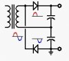
An easier way to double the voltage is to use a voltage doubler as shown in the attached circuit diagram (found elsewhere on the Internet).

This circuit is a half-wave rectifier with two capacitors which produce an output voltage that is twice the transformer secondary voltage, but the available current is only half the current that would be available from a half-wave rectifier by itself. This circuit placed between the magneto (white wire) and a 12v, 3-Watt incandescent bulb should work. The cost of the circuit and time involved in building it are insignificant. You can get the parts at Radio Shack. The output of the circuit will not be “clean” enough to charge batteries, and may not be clean enough to drive LEDs. But, you could probably clean it up enough for LEDs will a large filter capacitor across the output. Charging batteries would require voltage regulation as well.

For academic discussion purposes, if I had time to experiment with rewinding the white wire coil of a magneto to get 12v from it, I would assume the following as a place to start:

1) I need twice the length of the original wire, 2) but the new wire would be half the area of the original wire, 3) I would only expect to get half the current from the new coil, but 4) I would still get 3 watts of power from the new coil.

Based on the above, if the existing coil is 300’ of 26GA wire, which is 0.0159” in diameter and has an area of 0.000199in^2, then the new coil would be 600’ of 29GA wire, which has an area of about half of 0.000199in^2 and a diameter of about 0.0113”.

The diameter of the 29GA wire is 70% of the diameter of the 26GA wire, so I would expect the new coil to be larger in diameter than the original coil. This could be a problem, and may require rewinding the spark coil as well with smaller gage wire with the hope that enough of the wire could be put on in the space available so that the CDI work (anyone know if the CDIs are really that sensitive to voltage?).

I would probably build a coil-winding jig to facilitate nice flat and neat winds on the coil. The jig could be chucked into an electric drill operating at a slow enough speed that I could guide the wire by hand. This would be the only way to minimize the diameter of the coil.

The "academic discussion" above is speculation on my part ‘cause I haven’t had time to research it, and it’s based on what I remember from a power distribution class I took in engineering school a zillion years ago.
 

Attachments

Last edited:

Norco John

New Member
May 26, 2009
87
0
0
Brookston, IN
Alright I will not use that stuff but I did find a place to get any size wire that you need from ebay here is the link eBay Store - swords science treasures: Enameled Copper Magnet Tesla Tattoo Radio Coil Wire
Cool! He's got a great inventory, and if you get frustrated he'll sell you a sword to hack the mag to pieces with, too!

Something that hasn't been mentioned and is tickling in the back of my brain is the question of magnetic flux, that is, the ability of the magnet to induce a voltage in the windings. The reason the engine dies when you load too big a headlight bulb onto the white wire, even though the CDI is attached to the other winding is that the excess load in the lighting winding cause the magnetic field to collapse or something to that effect (it's been 25 years since I've studied generators and it's awful dusty up there in my brain)
Another variable on top of everything else you're dealing with.

Isn't research FUN?
 

reg454

New Member
Jan 11, 2009
269
0
0
42
michigan
I found some great reading about CDI's in this link not all of it relates here but their is alot of info concerning the magnetic flux created by the MAG and that you do need the two wire wraps in the MAG to get the voltage spike needed to run the CDI looks like I will have to rewind the coil with the common ground.

Electronic Ignition Overview