This post is to share a bright LED light system powered by the HT engine generator with the MB community. In my previous posts I described and showed pics of my original design. This post is about the re-design of that same system. This one is quite a bit simpler in terms of parts count and is a lot more compact. The goal was to develop: 1) a small electronic control module that would fit inside the body of a 3 x AAA battery type LED torch; 2) power a high intensity 3W white LED; 3) power a bright red LED tail light; 4) run off the generator white wire (w/ no battery); and 5) not interfere with the CDI so the engine will run at a slow idle with the lights on.
The system operates on an input voltage range of about 15V to 25V provided by the engine generator white wire. A full wave bridge rectifier converts the AC provided by the white wire to DC. The heart of the circuit is a switching current source that drives the white LED at 500mA. The tail light LED's are driven by a 50mA current sink. The switch incorporated in the end cap of the stock torch is used to turn the lights ON and OFF and FLASH.
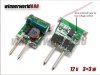
The LED driver module, the bicycle torch with tail light, and high intensity LED (I replaced the torch stock LED with a brighter one) were all found on eBay and came from China. I constructed most of the support circuitry with surface mount parts from Mouser. This allowed it to fit on a 0.7" X 0.5" Vector board (Radio Shack).
The system draws 160mA at 22 VDC (3.5 Watts). This is the voltage on the 1000uF filter cap at low driving engine speed. At idle, the output of the generator drops. The circuit responds by tapering the current draw down when the input drops below about 18 volts. The result is some flicker at idle when the lights are ON but this reduction in loading is what keeps the system from degrading the CDI at idle.
In the FLASH mode the current draw is only about 40mA. The head and tail lights blink at about 7 Hz with 20% duty cycle.
In actual operation, the head light is extremely bright. It throws a strong focused beam that I set at about 30 feet in front of my bike. The peripheral light is adequate to illuminate the off-center areas. I feel safe riding at 15 to 20 mph in total darkness. The tail light is very bright and highly visible in day and night conditions.
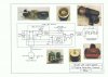
The attached is a schematic of the complete circuit including thumbnail photos of the major components.
I hope the results from my efforts will be useful to bike builders that like DIY projects. The hardest part was building the circuit with surface mount parts and point to point wiring. But with the right tools, steady hands, and magnification, it can be done.
Good luck
The system operates on an input voltage range of about 15V to 25V provided by the engine generator white wire. A full wave bridge rectifier converts the AC provided by the white wire to DC. The heart of the circuit is a switching current source that drives the white LED at 500mA. The tail light LED's are driven by a 50mA current sink. The switch incorporated in the end cap of the stock torch is used to turn the lights ON and OFF and FLASH.
The LED driver module, the bicycle torch with tail light, and high intensity LED (I replaced the torch stock LED with a brighter one) were all found on eBay and came from China. I constructed most of the support circuitry with surface mount parts from Mouser. This allowed it to fit on a 0.7" X 0.5" Vector board (Radio Shack).
The system draws 160mA at 22 VDC (3.5 Watts). This is the voltage on the 1000uF filter cap at low driving engine speed. At idle, the output of the generator drops. The circuit responds by tapering the current draw down when the input drops below about 18 volts. The result is some flicker at idle when the lights are ON but this reduction in loading is what keeps the system from degrading the CDI at idle.
In the FLASH mode the current draw is only about 40mA. The head and tail lights blink at about 7 Hz with 20% duty cycle.
In actual operation, the head light is extremely bright. It throws a strong focused beam that I set at about 30 feet in front of my bike. The peripheral light is adequate to illuminate the off-center areas. I feel safe riding at 15 to 20 mph in total darkness. The tail light is very bright and highly visible in day and night conditions.
The attached is a schematic of the complete circuit including thumbnail photos of the major components.
I hope the results from my efforts will be useful to bike builders that like DIY projects. The hardest part was building the circuit with surface mount parts and point to point wiring. But with the right tools, steady hands, and magnification, it can be done.
Good luck
Attachments
Last edited: