Going case inducted too!!!

Very well said Theon, I have been in this business for 50 year from go cart, mini bikes, street rod, motorcycles and now motorbikes. I have always enjoyed sharing my Ideas with other people in the field. I have never done this for money its just self satisfaction. Most people would never spend the time and effort to do the thing I do. And as far as China goes nobody has stopped them from copying anything in my life time and don't think anybody ever will.
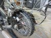
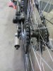
Anyway, I wanted to tell I used one of your ideas it was your disk brake adapter it came out perfect.
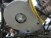
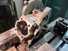
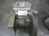
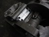
So I thought I would share something I made that I think you can use on your bikes with all that power. You know the flower nut on the clutch? well I made my own nut and shaft with a 5/16 lock nut on it. its a lot stronger that that flower nut.
 

Attachments

  • IMG_0320.JPG
    IMG_0320.JPG
    121.4 KB · Views: 235
  • IMG_0321.jpg
    IMG_0321.jpg
    135.2 KB · Views: 239
  • IMG_0322.JPG
    IMG_0322.JPG
    93.9 KB · Views: 250
I don't remember if I shared these pics, but this was my idea for stuffing the case halves, these plates were from a piece of .075" thick 7075 T6 aluminum that I spun down on my lathe until I had about .020" clearance on each side of the crank, they are a really tight fit into the case and then I drilled thru the case and into the plates, tapped the plates for M4 bolts, then drilled the case holes slightly larger to clear the bolts. This is the same idea Theon did but his are pressed in and held in place with Devcon or red locktite if I remember right, and mine are bolt in on this engine.
I do plan on remaking these plates tho since the cutouts around the bearings are a bit sloppy and my CNC router should be able to do a much better job. I still want these to be a tight fit just in case a bolt backs out but they'll also be bonded into place with Devcon or brazed in with Alumaloy before I run this engine for sure.
These are old pics, but they show how I was planning on stuffing the case...
The outside case pics show the screws that hold the plates in place, sorry for the huge pics but have no clue how to resize them right now...

hl95.jpg


iyw1.jpg


zq02.jpg
 
I'm really liking that disc brake adapter and it looks like it's pretty easy to do on the lathe.. I've been looking for a way to put a rotor on mine for some time now since the V brakes don't work so well when ya get past 30mph or so... I've been lucky so far with my full speed runs on a road where there's no side streets for people to pull out in front of me etc, but just slowing down to pull into my shop parking lot is enough of a scare from 40mph and the brakes begin to fade fast...
 
One way I was going to do the disc brake on mine was by using a 42 tooth flat sprocket and running the caliper over the sprocket it's self, but that leads to other issues like keeping the chain well lubed without getting any chain lube on the part the brake pads ride on...
 
Davezilla, Nice job on the cases. I was thinking of doing something like that but with the cups I made I might not have to. I made a sprocket brake before I made the adapter for this one. It didn't work, one reason was the one you mentioned the other was the caliper would spread when you put on the brakes. That why I when this route. This adapter works with the rag joint and is center with a hole that fits around the end of the hub. It work great!! I tried to load a picture of the sprocket brake but it didn't work, I try again later.
 
Hey guys I just wanted ta let ya know that I'm really liking this thread ... great ideas as well as some really good advice and 'know-how' being shared ... nice too see and am looking forward ta the out come ...
 
Yeah, I got the idea of the sprocket brake from the Harley world where some custom jobs use a sprotor in back to save weight and clutter around the rear wheel, Of course, these are belt driven so no oil or grease in the area and use a special caliper that's wide enough, They do make them for chain drive too but mostly for show bikes or o ring chains that are lubed and sealed at the factory, but the smallest o ring chains available are the 520 chains which are way too big for what we're doing.
 
Of my disc brake setups, the center lock adaption on the Dual Sus bike is my favorite, limited by the availiability of mostly only 32 spoke hubs, but neat, easy to work on and has not given me any trouble.
I found a bike with wanted hubs at a pawn shop, swapped out the wheels and brakes I wanted and gave the rest to a mates kid. Cost me about $100, and the bike was still worth the same after the swap.
 
Theon, We have a place called recycled cycles they have used parts I usually go over there and get brake parts. I've got a couple of calipers and master cylinders for like 20 to 30 dollars per pair. We also have a scrap yard in town where I get most of my bike parts and metal. Well back to the shop.
 
That's a cool looking tadpole you got there... yeah, I see how you did the rear brake and that's the same I was thinking about but decided against it since I couldn't find a solution for the chain lube problem and running a chain dry makes them very shrot lived...

I'm really liking the way you made that gas tank as part of the rear fairing...
 
Sweet looking ride!!
Looks like it's nice and stable sitting really low and close to the ground too... I bet those thngs can really go with a good electric motor setup installed... How many watts is the motor you're looking to install?
 
The motor I want is a magic ple4 with a 48 volt battery if I can save some money. I could just buy the motor and have someone lace the wheel that might be cheaper. I think its 500 to 1000 watts. The battery is the most money.
 
I got a little work done today I made a plate to go where the manifold will bolt to the case. It will be screwed and glued with davcon. I'm waiting for the manifold to arrive before cutting any more holes.
 

Attachments

  • IMG_0323.JPG
    IMG_0323.JPG
    138.3 KB · Views: 231
  • IMG_0325.JPG
    IMG_0325.JPG
    90.8 KB · Views: 241
  • IMG_0326.JPG
    IMG_0326.JPG
    85.9 KB · Views: 213
Nice looking progress... I can't tell from the pics if you scribed a line where your case split line is or if that's 2 separate plates you got bolted down on the cases?

Anyway, looks like you got a good plan for mounting the reed box...
 
It's two separate plates. It will also have heli-coils to hold the reed block on that will give it a little more strength. I will wait for the reed block to come now. I have been looking at bearings for the cases and the wrist pin, I will order them soon. I'm also looking at carburetors too.
 
Good idea to wait for the reed block before any further cutting is done, and you definitely want to center the reed block over the split line as much as possible, and keep the port as centered between the crank wheels as possible to prevent an internal turbulence or partial blockage that could restrict your top end if you decide to go really big with the carb.
Nice work so far and you're really sparking my interest to open up my boxed up parts again... lol
 
Back
Top