Bike Bobber

Well, I'd say your 'eyeballs' are working just fine. Show us the finished product.

Tom

I'll be happy to show the finished product 2door... when I finish it. lol I started with a sketched design and the project has taken on a life of it's own. I really don't know when it will be done, or what it will exactly look like. I work on it a little each day and post as I go.
dance1
 
After deciding where the bracket will be located on the frame rail I made 4 simple patterns out of poster board to transfer to the stock and cut out the mounting brackets because the rail is not round it is oval shaped and tapered. My band saw has a 1/2 in. blade so I can't just cut circles and arcs. I have to cut slots first and than work my way around the pattern. Remember to stay away from the lay out lines.
 

Attachments

  • 063_the bracket will be placed here.JPG
    063_the bracket will be placed here.JPG
    131.6 KB · Views: 121
  • 064_start with a simple pattern to follow.JPG
    064_start with a simple pattern to follow.JPG
    120.4 KB · Views: 132
  • 065_starting 1st brake arm bracket strap.JPG
    065_starting 1st brake arm bracket strap.JPG
    198.6 KB · Views: 124
  • 077_can't saw curves to cut slots.JPG
    077_can't saw curves to cut slots.JPG
    213.6 KB · Views: 123
  • 078_now cut out the slots.JPG
    078_now cut out the slots.JPG
    183.7 KB · Views: 124
After sawing out 3 of the 4 bracket blanks on the band saw I secured them in the bench vise and roughed them out with a carbide bit in a dremel tool. Then I finished them with a hand file. I filed a little and checked the fit often.
 

Attachments

  • 079_roughing out with dremel.JPG
    079_roughing out with dremel.JPG
    126.3 KB · Views: 121
  • 081_finish with a file.JPG
    081_finish with a file.JPG
    132.2 KB · Views: 127
  • 086.JPG
    086.JPG
    183 KB · Views: 130
  • 088.JPG
    088.JPG
    161.3 KB · Views: 144
  • 089.JPG
    089.JPG
    130.3 KB · Views: 143
Once I was satisfied with the fit of the inside of the brackets on the frame rail I moved to shaping the outside of the brackets. I end milled each bracket to it's overall width in relation to the center line of the frame rail. It is always a good idea to lay out your design on your work piece. You can do this easily using Dykem lay out fluid, a scriber, and a scale.
 

Attachments

  • 090.JPG
    090.JPG
    146.6 KB · Views: 140
  • 091.JPG
    091.JPG
    220.8 KB · Views: 146
  • 092.JPG
    092.JPG
    125.8 KB · Views: 128
With the brackets squared up and laid out it is time to drill and tap some holes. The holes must be precisely located so I secured one bracket in a power lock vise on the mill and set up a "table stop". This will precisely located each bracket in the vise every time. Then I picked up 2 sides of the bracket (locate the edge of the work piece and set the machine dial at "0". These 2 locations are called "datum's". All measurements are taken from the datum's. I'm using an edge finder commonly known as a "wiggler" to pick up the edge's. This is not as precise as other methods but is faster and close enough for this application. After moving the x and y axis (the machine table) to the desired location of the hole. Always move to locations in a clockwise direction. Lock the table in place. Don't reef on the locks, just enough pressure to secured them in place.
 

Attachments

  • 093.JPG
    093.JPG
    166.1 KB · Views: 112
  • 094.JPG
    094.JPG
    130.6 KB · Views: 129
  • 095.JPG
    095.JPG
    136.1 KB · Views: 127
Now we're ready to poke some holes. The inside bracket's get tapped holes and the outside get through holes. Since the hole locations are symmetrical on the bracket's it is just a matter of flip flopping the brackets in the vise and gently pushing them against the table stop before closing the vise. First spot drill each of the 8 holes in the 4 brackets. Than drill & tap 2 holes, and drill 2 holes through.
 

Attachments

  • 096.JPG
    096.JPG
    152.2 KB · Views: 129
  • 097.JPG
    097.JPG
    167.7 KB · Views: 147
  • 098.JPG
    098.JPG
    140.4 KB · Views: 130
  • 099.JPG
    099.JPG
    147.2 KB · Views: 117
  • 100.JPG
    100.JPG
    133.7 KB · Views: 126
After finishing the holes I used the band saw and belt sander to shape the outside of each bracket. As always I finished them off with a hand file. I mounted them on the frame rail to check the fit again before moving on to the next step. Good fit...
 

Attachments

  • 101.JPG
    101.JPG
    128.5 KB · Views: 133
  • 102.JPG
    102.JPG
    228 KB · Views: 145
  • 103.JPG
    103.JPG
    135.2 KB · Views: 139
  • 104.JPG
    104.JPG
    146.8 KB · Views: 157
  • 105.JPG
    105.JPG
    144.2 KB · Views: 153
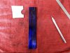
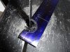
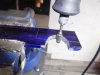
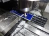
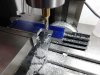
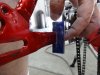
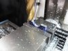
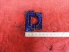
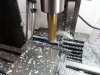
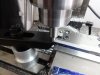
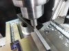
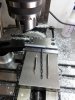
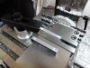
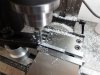
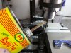
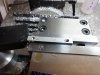
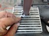
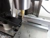
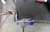
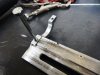
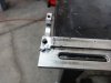
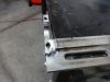
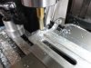
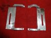
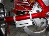
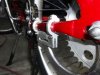
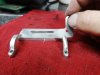
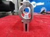
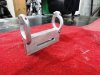
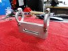
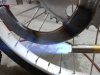
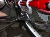
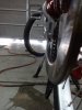
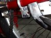
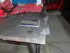
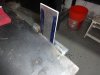
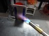
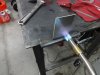
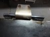
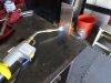
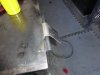
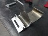
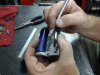
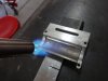
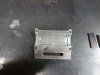
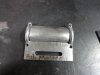
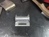
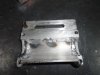
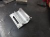
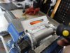
Next I'm going to weld the clamps to the slot bracket. I could have screwed everything together, but that would be even more time consuming. Besides we all know that anything that screws together on a MB comes unscrewed. I machined 1/4 in. slots in the ends of the bracket so it would be easy to square up the clamps on the bracket when welding. Whenever you butt weld two piece's together you should always chamfer the edges first. It makes for a much stronger weld. I had to lay down some weld near the clamp holes. This can be tricky at best and a disaster at worst. Hear is a little trade secret I'll share; put the solid end of a drill bit or the flat end of a transfer punch in the hole before welding. I used a steel transfer punch, if you are welding steel use a piece of brass in the hole. This will help transfer the heat off the wall of the hole and keep the weld puddle from flowing into the hole. This method is not fool proof, it takes practice.
 

Attachments

  • 107.JPG
    107.JPG
    123.5 KB · Views: 133
  • 108.JPG
    108.JPG
    127.4 KB · Views: 144
  • 109.JPG
    109.JPG
    133.3 KB · Views: 125
  • 110.JPG
    110.JPG
    116.1 KB · Views: 129
  • 111.JPG
    111.JPG
    114.6 KB · Views: 142
After welding the 4 clamps to the bracket I used the mill to remove most of the weld bead and than finished blending in with a file. Aluminum is easy to blend in and shape with a file. As always I did a test fit and it looks pretty good.
 

Attachments

  • 112.JPG
    112.JPG
    133.2 KB · Views: 123
  • 113.JPG
    113.JPG
    173.5 KB · Views: 130
  • 115.JPG
    115.JPG
    168.1 KB · Views: 133
  • 116.JPG
    116.JPG
    157 KB · Views: 133
  • 117.JPG
    117.JPG
    130.6 KB · Views: 120
Now I'm going to do a little grinding and filing on the clamps to give them a softer look. I'm using a 1/4 in. radius gauge as a guide. I started out using the die grinder, but was concerned that I might snag the metal and bend the crap out of the bracket before it is finished. So I picked up one of my favorite tools and filed them by hand. It doesn't take long to remove aluminum with a file.
 

Attachments

  • 118.JPG
    118.JPG
    151.6 KB · Views: 152
  • 119.JPG
    119.JPG
    158.5 KB · Views: 132
  • 120.JPG
    120.JPG
    166.8 KB · Views: 143
  • 121.JPG
    121.JPG
    170 KB · Views: 132
That's some really nice work... Glad to see some people still take their time and get everything just perfect. This is going to be an awesome build
 
I'd like to pull a marathon in the shop uninterrupted and finish it... The forum is not an interruption, it is an inspiration.
Anyway... Next I fit the arm to the bracket. This required a little heat to bend the arm to line up with the slot bracket.
 

Attachments

  • 122.JPG
    122.JPG
    151 KB · Views: 140
  • 123.JPG
    123.JPG
    146.1 KB · Views: 124
  • 124.JPG
    124.JPG
    162.3 KB · Views: 141
  • 125.JPG
    125.JPG
    130.1 KB · Views: 126
  • 126.JPG
    126.JPG
    148.3 KB · Views: 147
Now that the arm is fit to the bracket I'm going to set it aside again and finish the bracket. I cut a rectangle out of a sheet of 1/8 in. aluminum wide enough to fit between the bracket clamps. Next I heated and bent the piece over a steel bar welded to my table. Aluminum melts at 900 degrees F, but unlike steel it doesn't change colors when it gets hot and when it cools down.
When heat is applied to the surface the surface will become dull. Just moments before it melts it will get a orange peel texture on the surface and than it will simply fall apart like an old sponge. Sometimes when you mistakenly bend the metal parallel to the grain... opps it cranks. This is a rookie mistake, but it will serve well as an example of what not to do.
 

Attachments

  • 129.JPG
    129.JPG
    160 KB · Views: 124
  • 130.JPG
    130.JPG
    145.7 KB · Views: 114
  • 132.JPG
    132.JPG
    133.2 KB · Views: 133
  • 133.JPG
    133.JPG
    149.6 KB · Views: 134
  • 134.JPG
    134.JPG
    115.5 KB · Views: 128
I cut a new piece of aluminum. You can see the grain in the metal. Always bend perpendicular to the grain. Bending over the round stock will get me close to where I need to be. It looks real close I'll fit it when I tack it together.
 

Attachments

  • 136.JPG
    136.JPG
    98.4 KB · Views: 121
  • 137.JPG
    137.JPG
    163 KB · Views: 116
  • 141.JPG
    141.JPG
    147.3 KB · Views: 116
  • 142.JPG
    142.JPG
    152.7 KB · Views: 145
I scribed a line where I'll saw off the excess metal and use it for the other side of the bracket. Fitting the gusset so that it will not interfere with the clamping of the bracket will take a little finesse. Always clean the area to be welded with a wire brush and when ever possible warm up the aluminum before welding. It doesn't need to be scorching hot, just warm it up. This will allow the use of less heat and the puddle will form faster and move easier. Notice in the last pic the orange peel on the curved gusset surface... almost most blew through it with the torch.
 

Attachments

  • 143.JPG
    143.JPG
    149.8 KB · Views: 124
  • 146.JPG
    146.JPG
    114.4 KB · Views: 133
  • 147.JPG
    147.JPG
    157.6 KB · Views: 124
  • 148.JPG
    148.JPG
    150.4 KB · Views: 138
I really didn't need to weld both the inside and outside of the bracket, but I did anyway. I hand filed the inside of the gusset first and made sure it still fit the bike. I roughed out the outside with my trusty dremel and a carbide bit.
 

Attachments

  • 149.JPG
    149.JPG
    151.6 KB · Views: 129
  • 150.JPG
    150.JPG
    148.1 KB · Views: 118
  • 151.JPG
    151.JPG
    133.9 KB · Views: 134
  • 152.JPG
    152.JPG
    128.3 KB · Views: 133
  • 153.JPG
    153.JPG
    170.6 KB · Views: 126
A master piece... really? That must be why it's taking so long....lol I have less than 5 bucks in material and supplies and over 40 hours of my time into it so fare. Anyone want to buy brake arm / bracket for sets for $500 a pop? LMAO
 
Back
Top