Weedge1212
New Member
Hello everyone,
The project I am currently working on is a motorized deer kart. I have a 24cc 2-stoke engine off of a stihl weed wacker. Although this is not a trike or tandem, i am hoping this is the right place to post this build. This project is not yet completed and I am posting it here to get some tips along the way. Here are some pictures of the cart itself
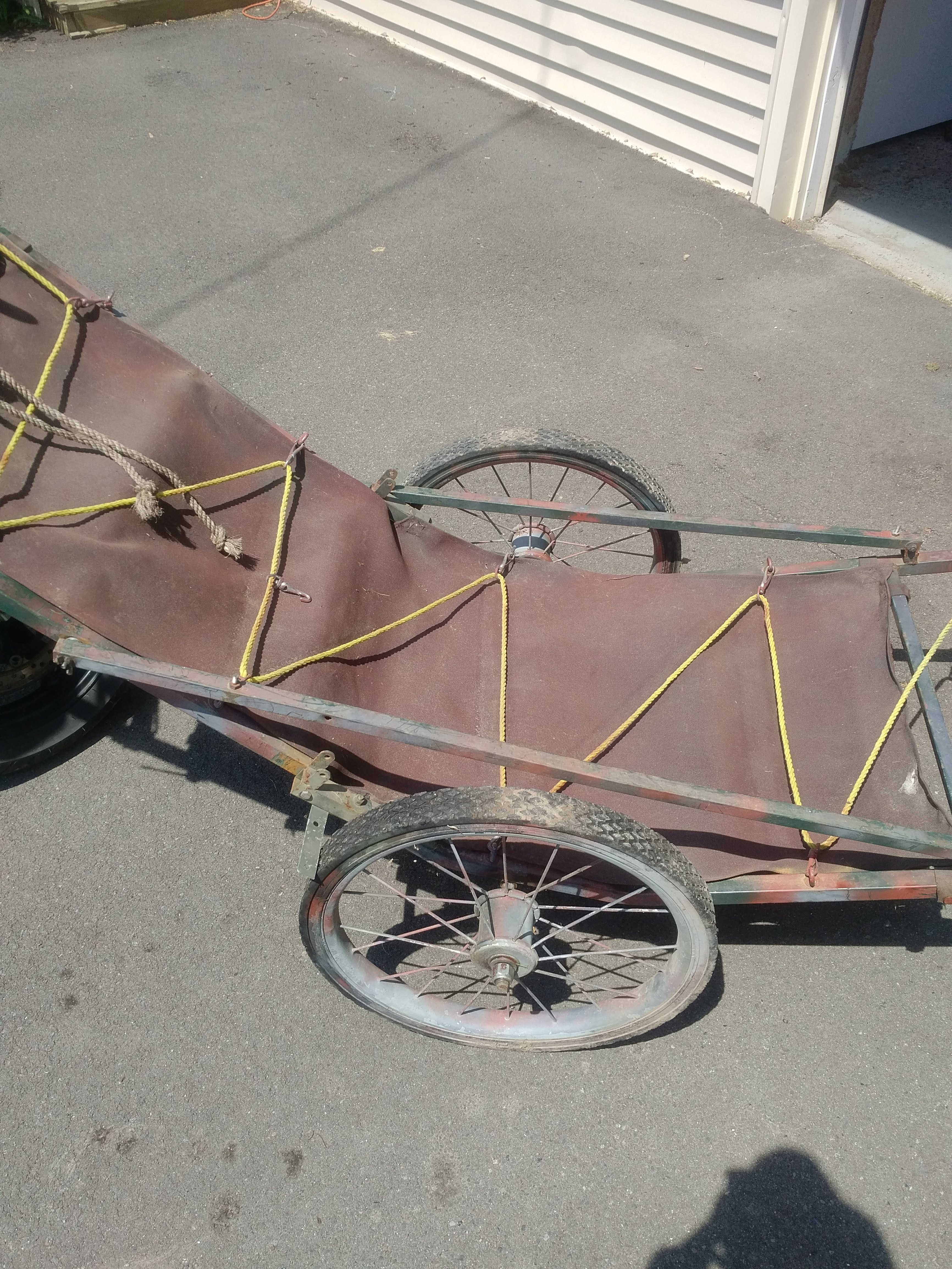
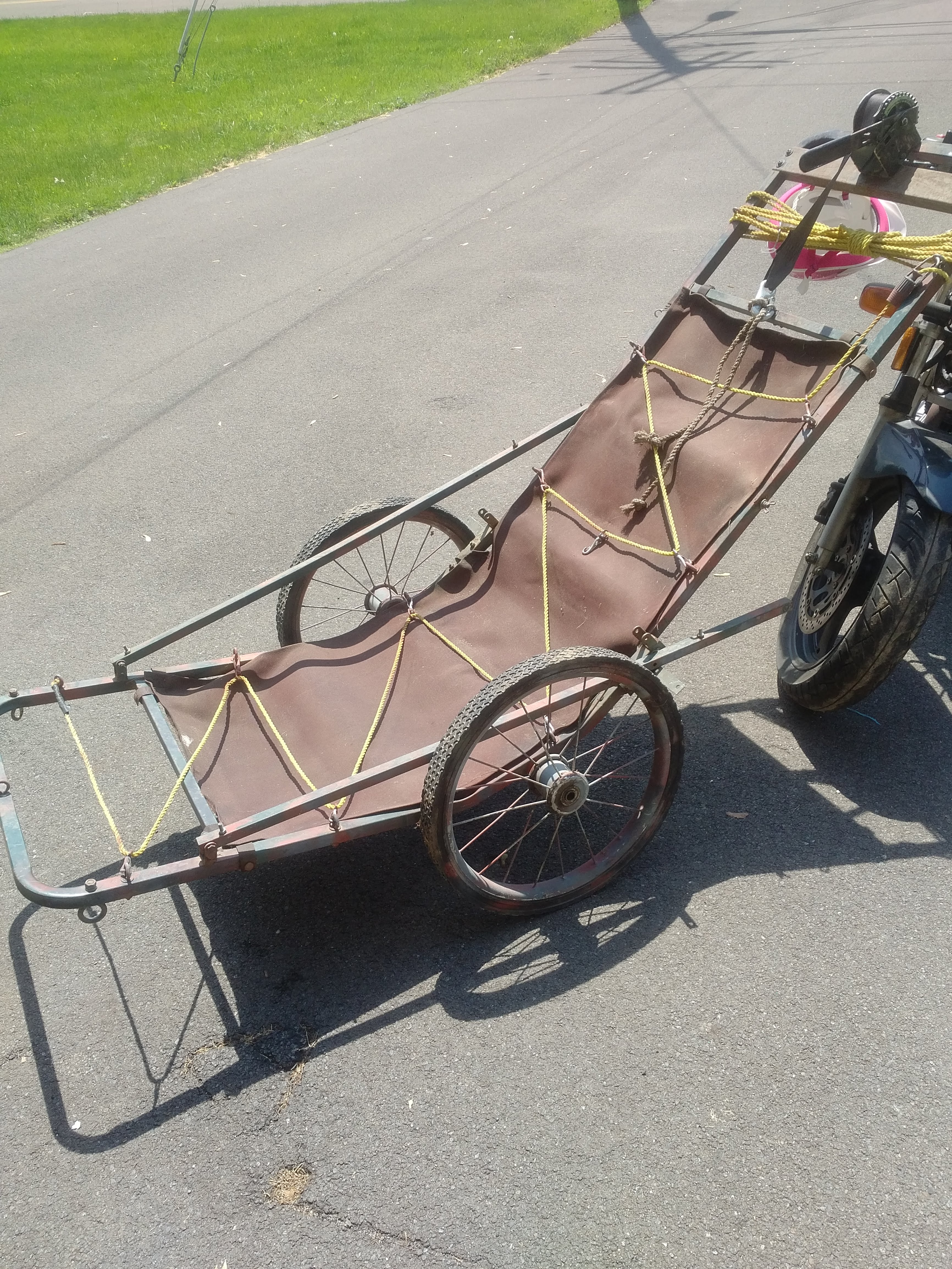
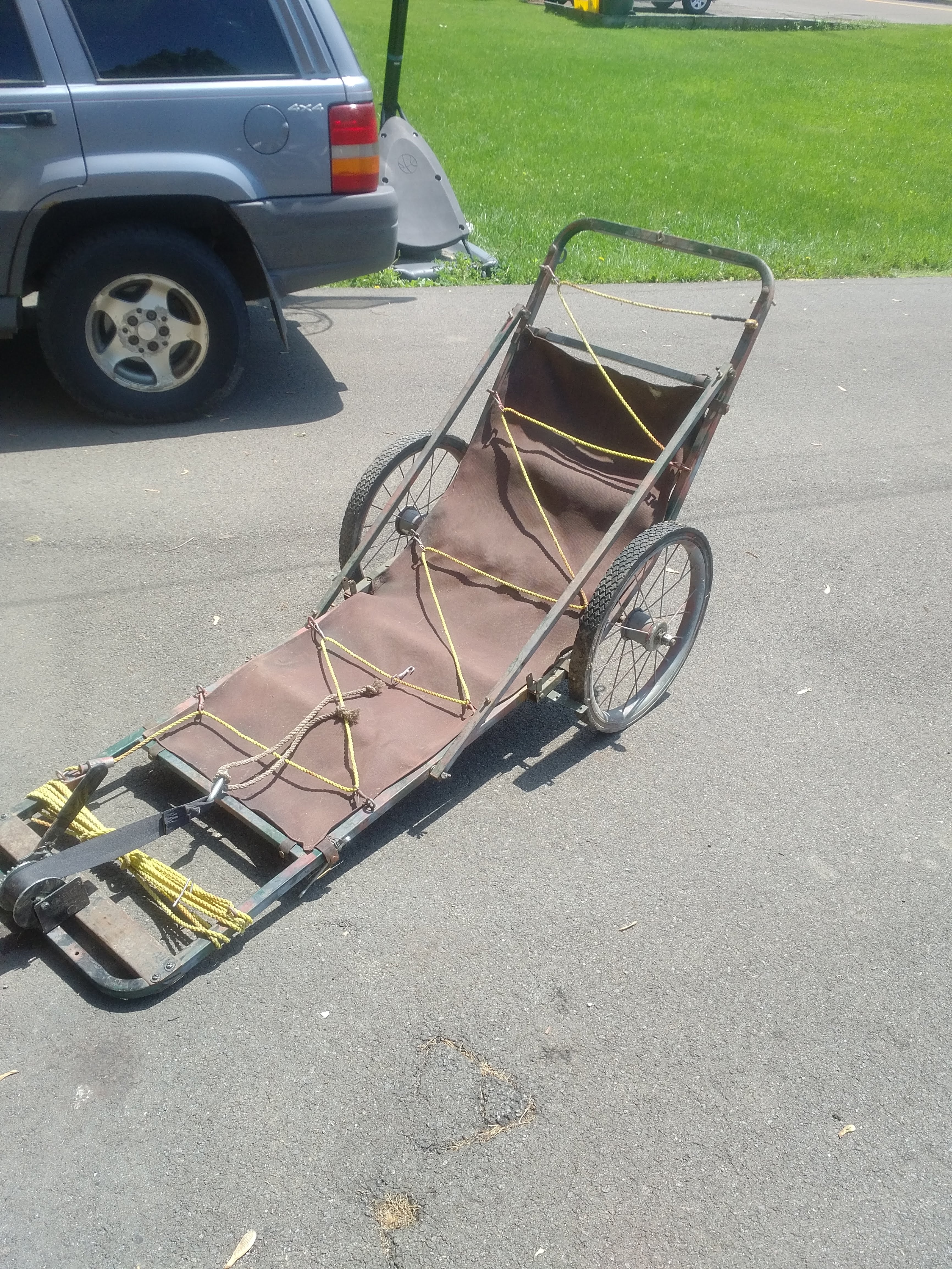
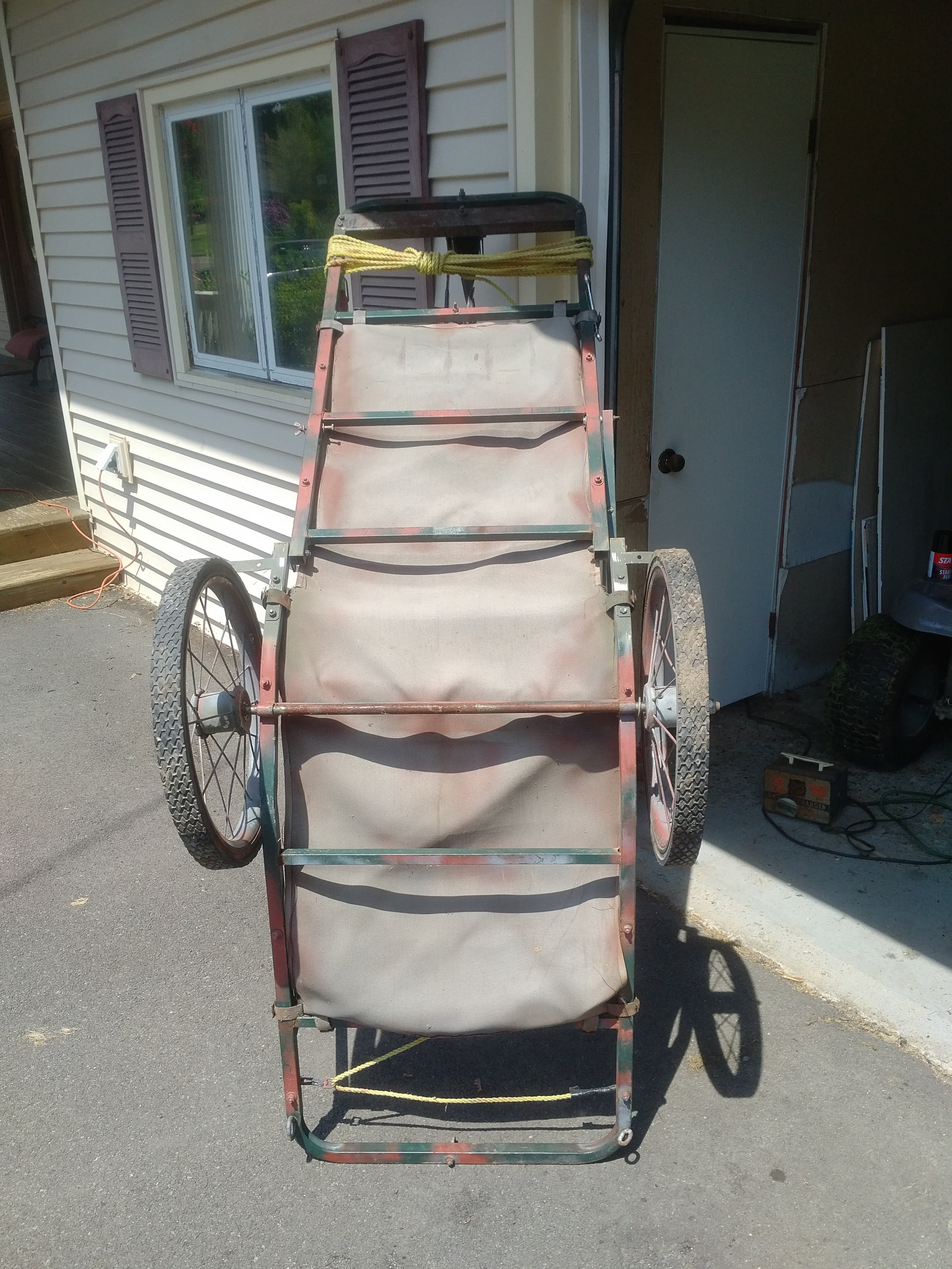
I got this kart off of craigslist for $40. Which I thought was a great deal. The kart is much more heavy duty than a lot of other ones I've seen. It also came with the hand crank winch attached which I thought was an awesome feature. I intend to have my chains and sprockets positioned so that I can still fold the kart up for transportation. I would like to use this kart for hauling deer out of the woods but it will probably be used more for hauling beer and gear in and out of camp.
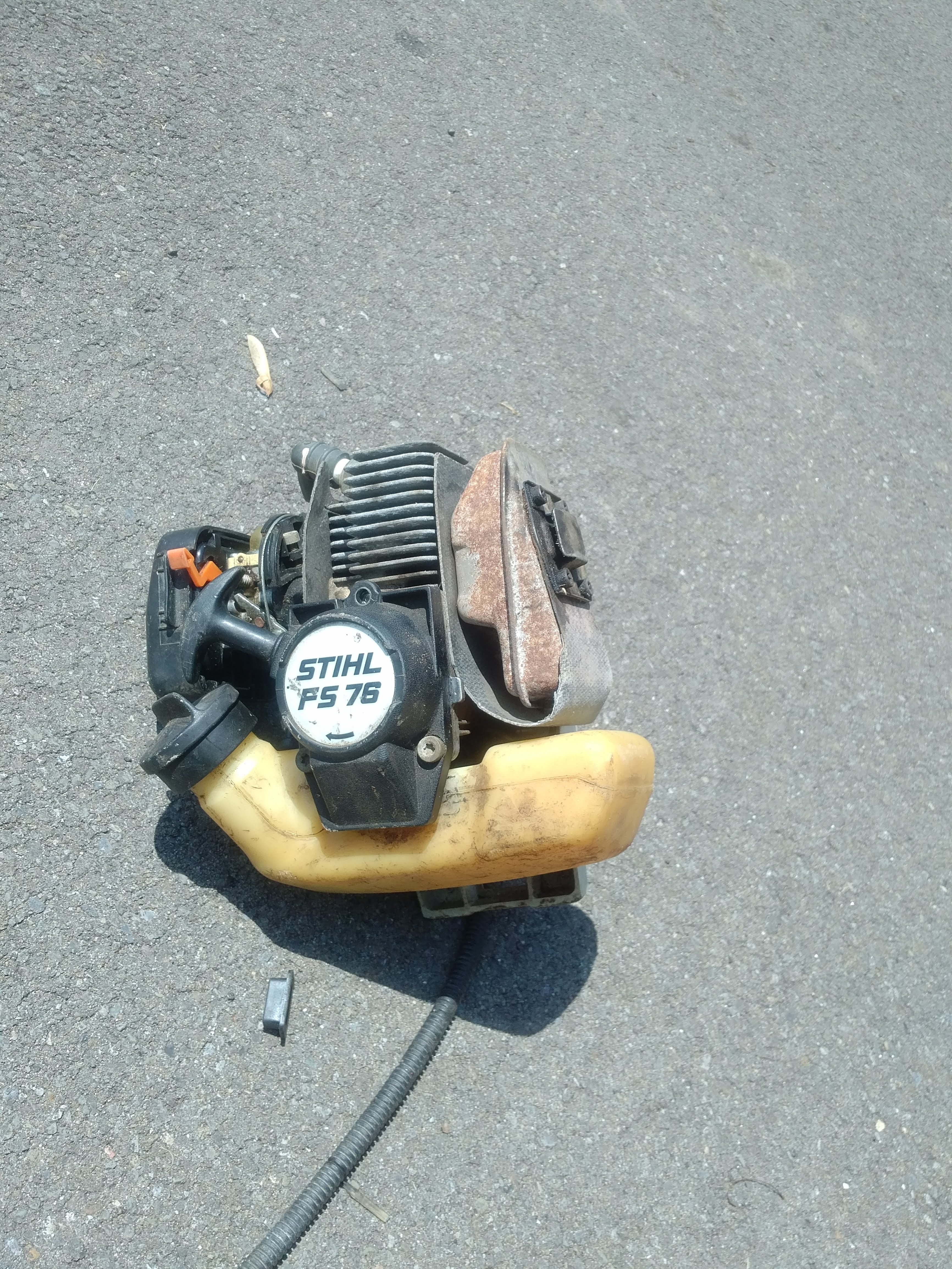

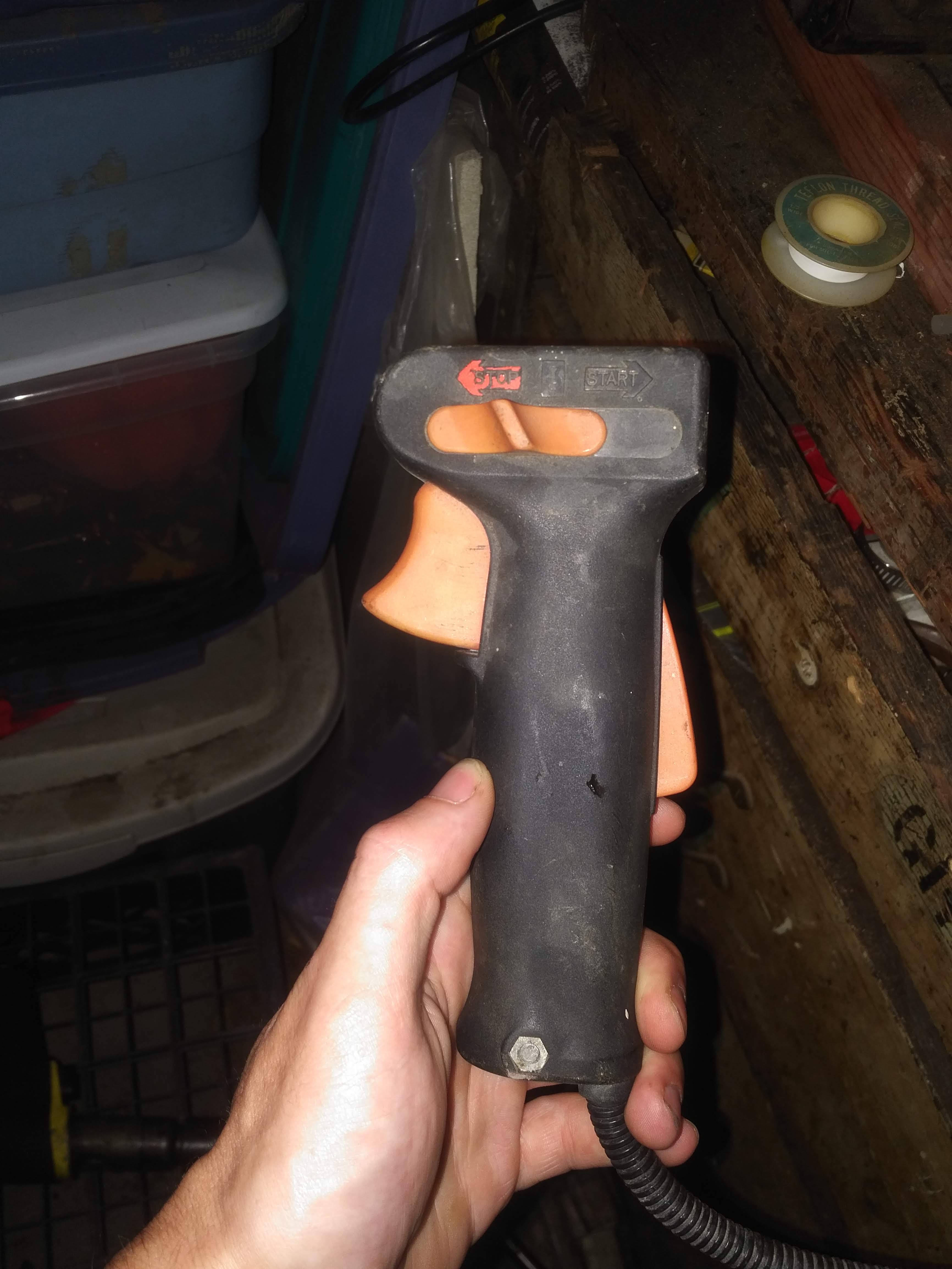
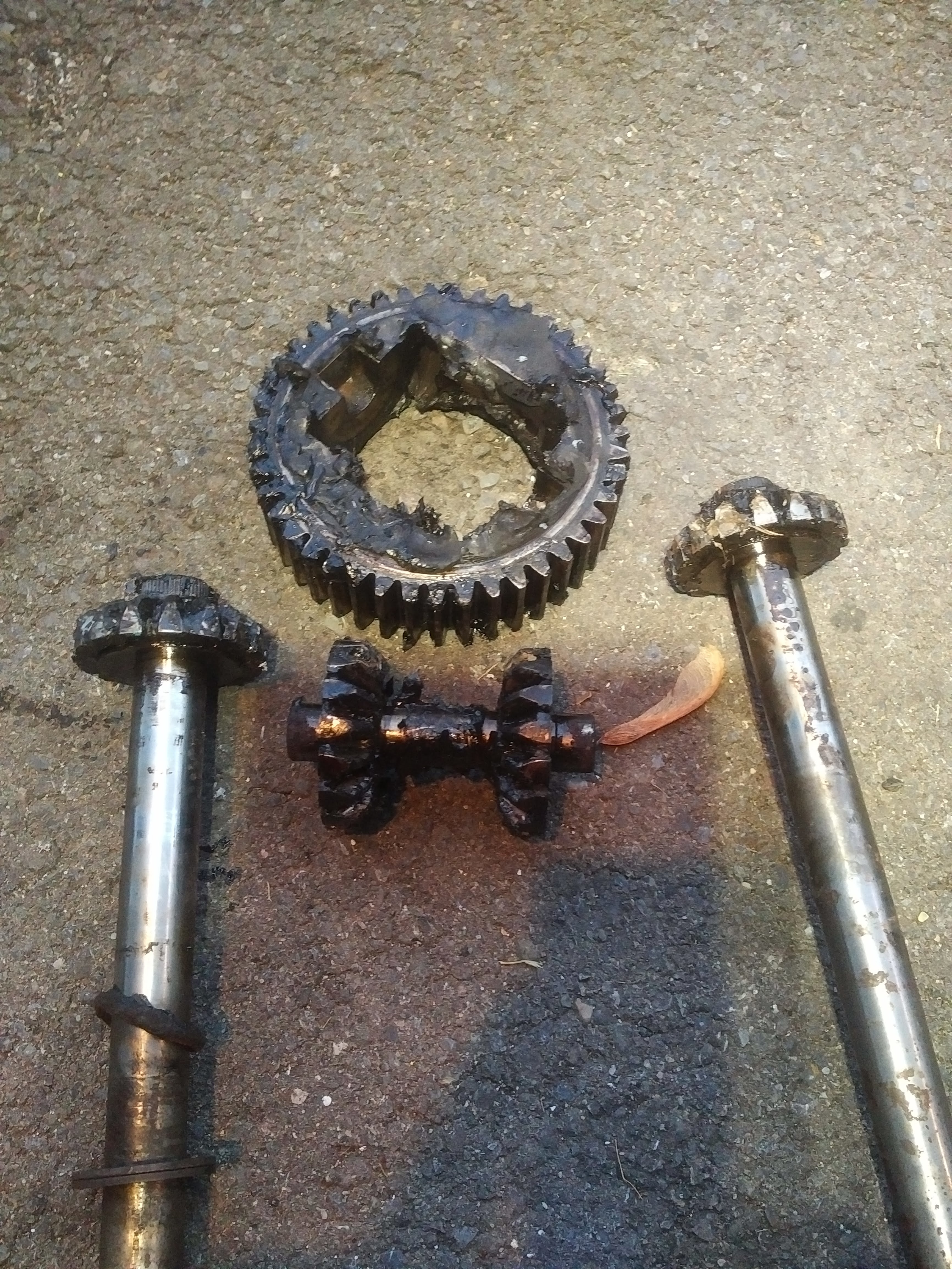
The stihl trimmer was being thrown out so i grabbed it and got the engine running. The engine only needed a carb cleaning and a new primer bulb. I saved the engine, clutch housing, and throttle control with a kill switch. The rest of it I threw away. So all together I have about $45 into this. I am trying to keep this project as cheap as possible. I got some scrap angle iron for free that I am going to use for mounting the engine and creating a mounting bracket for the jackshaft. I also have some axles from a riding mower than I plan on using for the shaft of my jackshaft. But I know the sprockets, chains, pillow block bearings are going to be my main cost (none of which i have ordered as of 6/1/18). I have to include a jackshaft to get the gearing low enough. This cart only needs to go walking speed and not much faster than that. So here is a sketch up I did for the drivetrain and gearing plans.
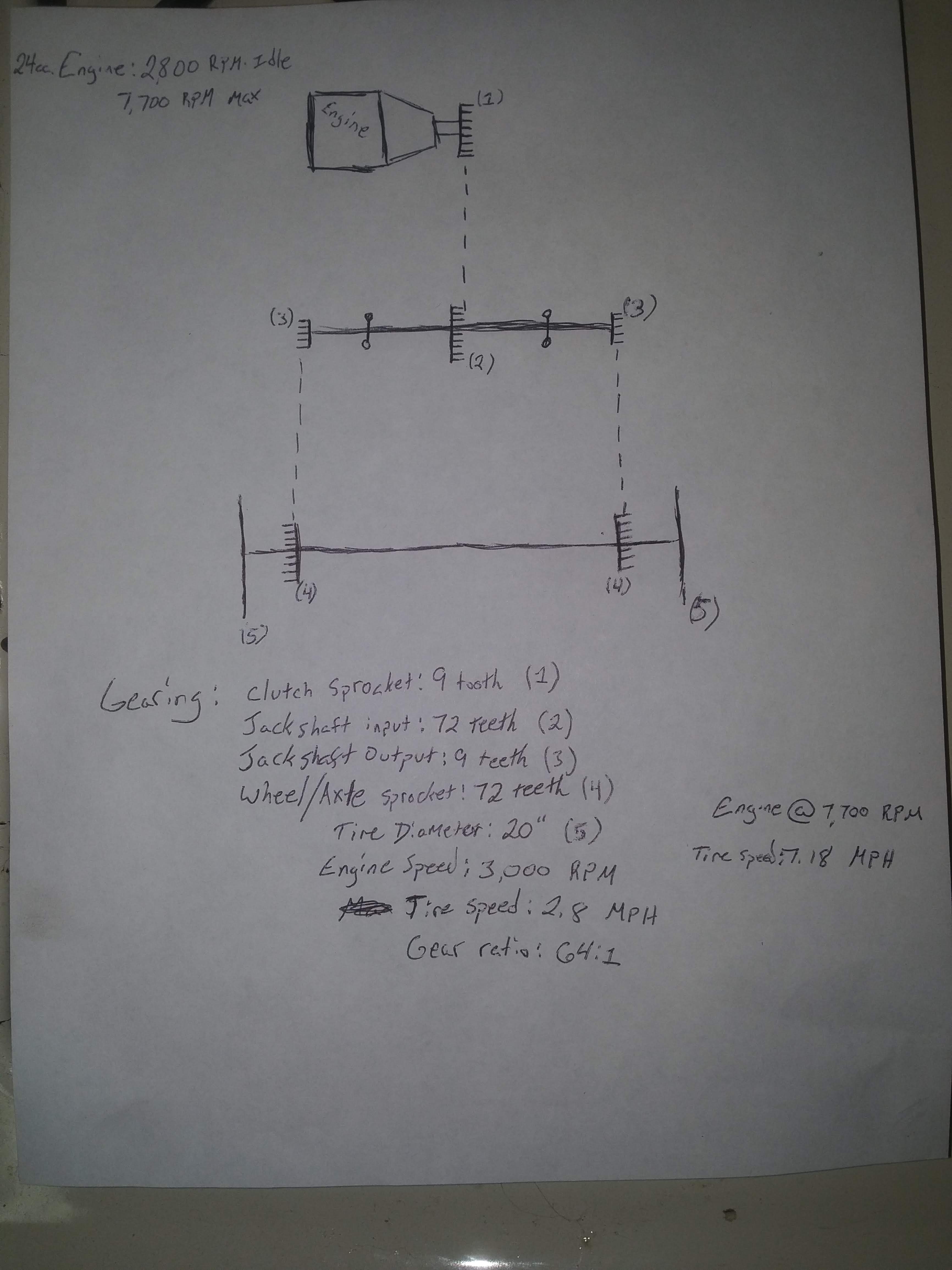
I used a gearing calculator https://www.electricscooterparts.com/motor-jackshaft-wheel-gear-ratio.html to determine the sprocket sizes I will need to achieve a speed of about 3 MPH. The engine idles at 2800 rpm. So I assume the clutch will engage at 3000 rpm, or atleast close to it. If I use sprockets with 9 teeth to 72 teeth twice, clutch to jackshaft and then jackshaft to wheels, it will go about 2.8 MPH. Just slightly under the 3 MPH I was shooting for. I was able to find the owners manual online and that says the engine has a max of 7,700 RPM. So at 7,700 RPM it should be going about 7.18 MPH. Which is close to running speed. This comes out to be a 64:1 gear ratio. I figure this will give me a good range of speed all the way through the throttle. If someone knows of different gearing that would work better than please let me know.
One thing I'm not completely sure of is how I am going to attach the sprockets. First off is the clutch.
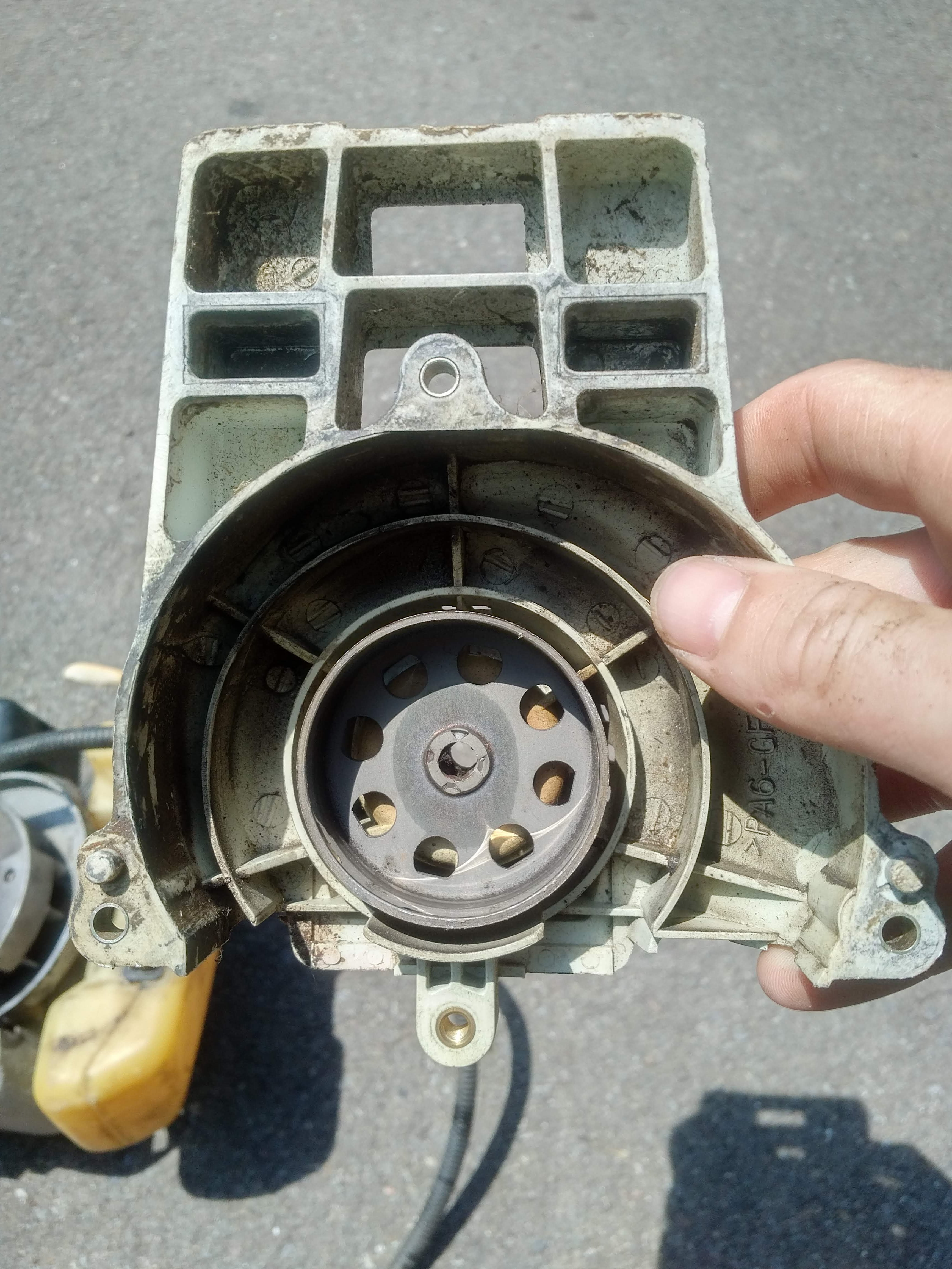

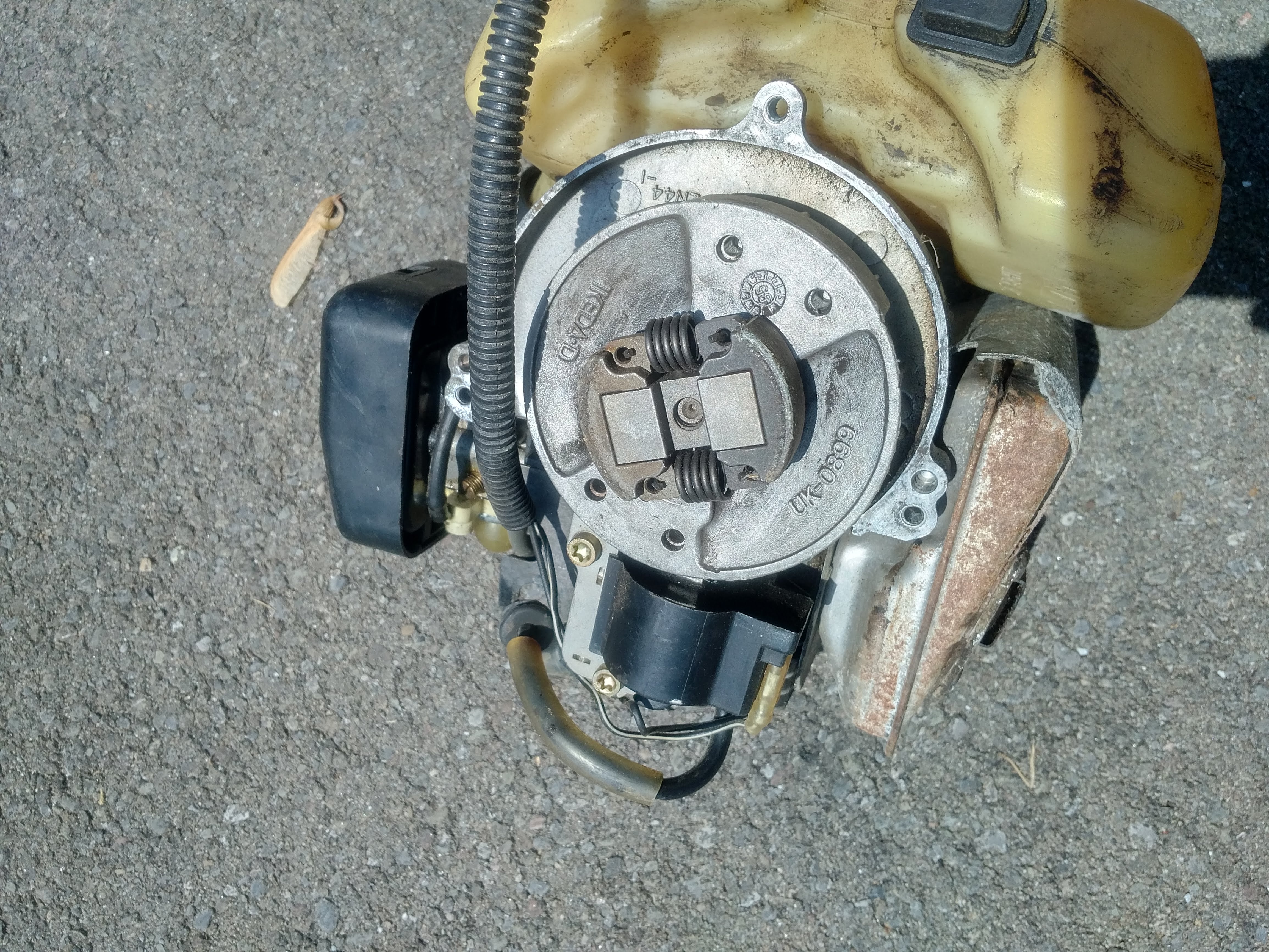
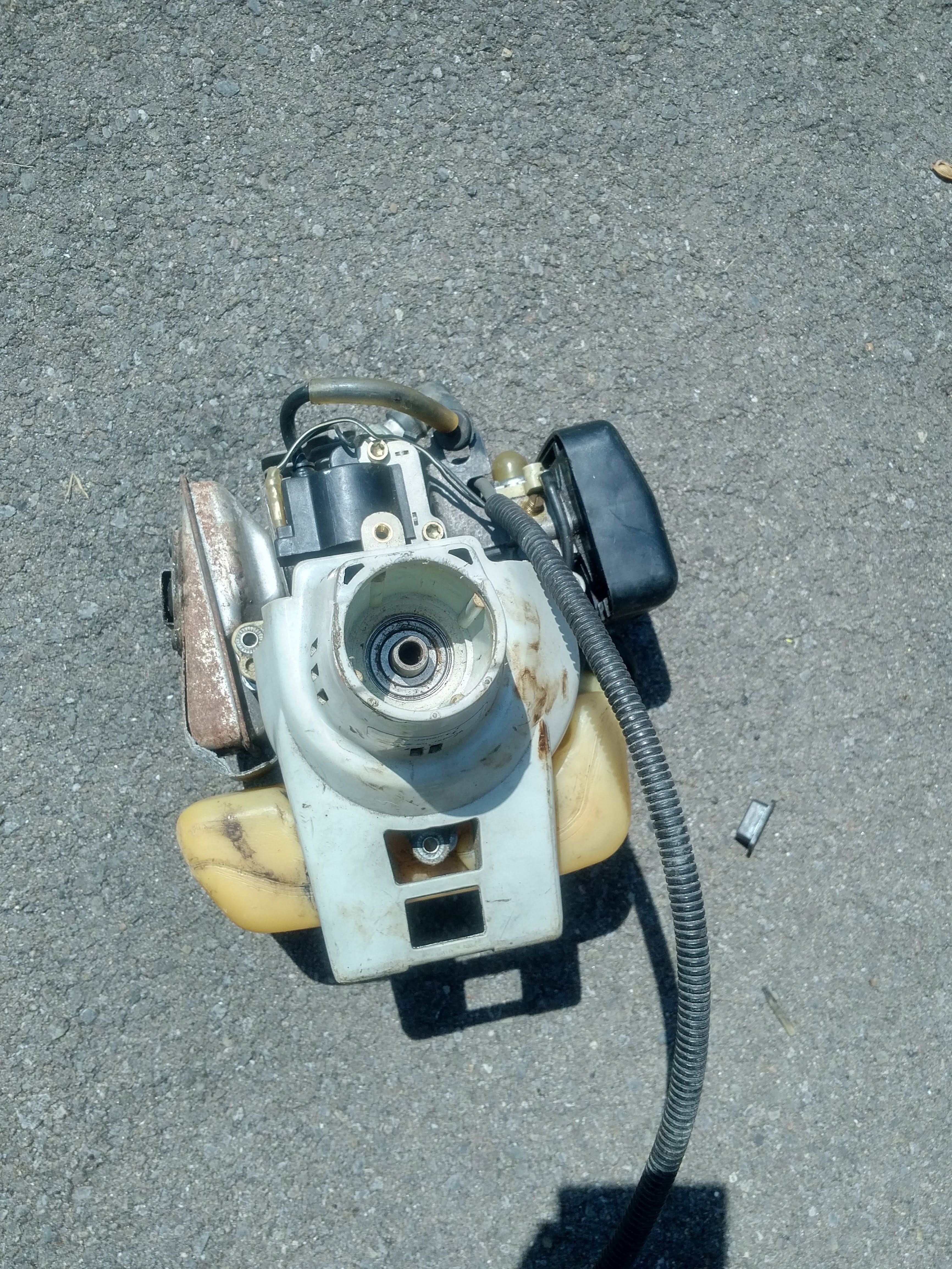
As you can see in the pictures, the clutch drum has a square hole. So I suppose I just need to find some steel rod that i can square off on my bench grinder and use a type B sprocket to attach it to the squared rod. This rod also has to be strong enough not to twist or bend when this kart has a deer on it and an engine spinning at 7,000 rpm. Which make me question if this is the way to go. If any of you guys have a better suggestion on how to attach the sprocket to the clutch, please let me know.
I also question if this clutch will be able to handle the load of this kart. I don't know for certain, but i don't think this kart will have much more than 150 lbs on it. Again, I'm sure someone on this forum has a lot more experience with these centrifugal clutches than I do. So if this clutch is just going to start slipping the minute I put some weight on it, than please let me know what modifications I can do to it or if I should look into something completely different.
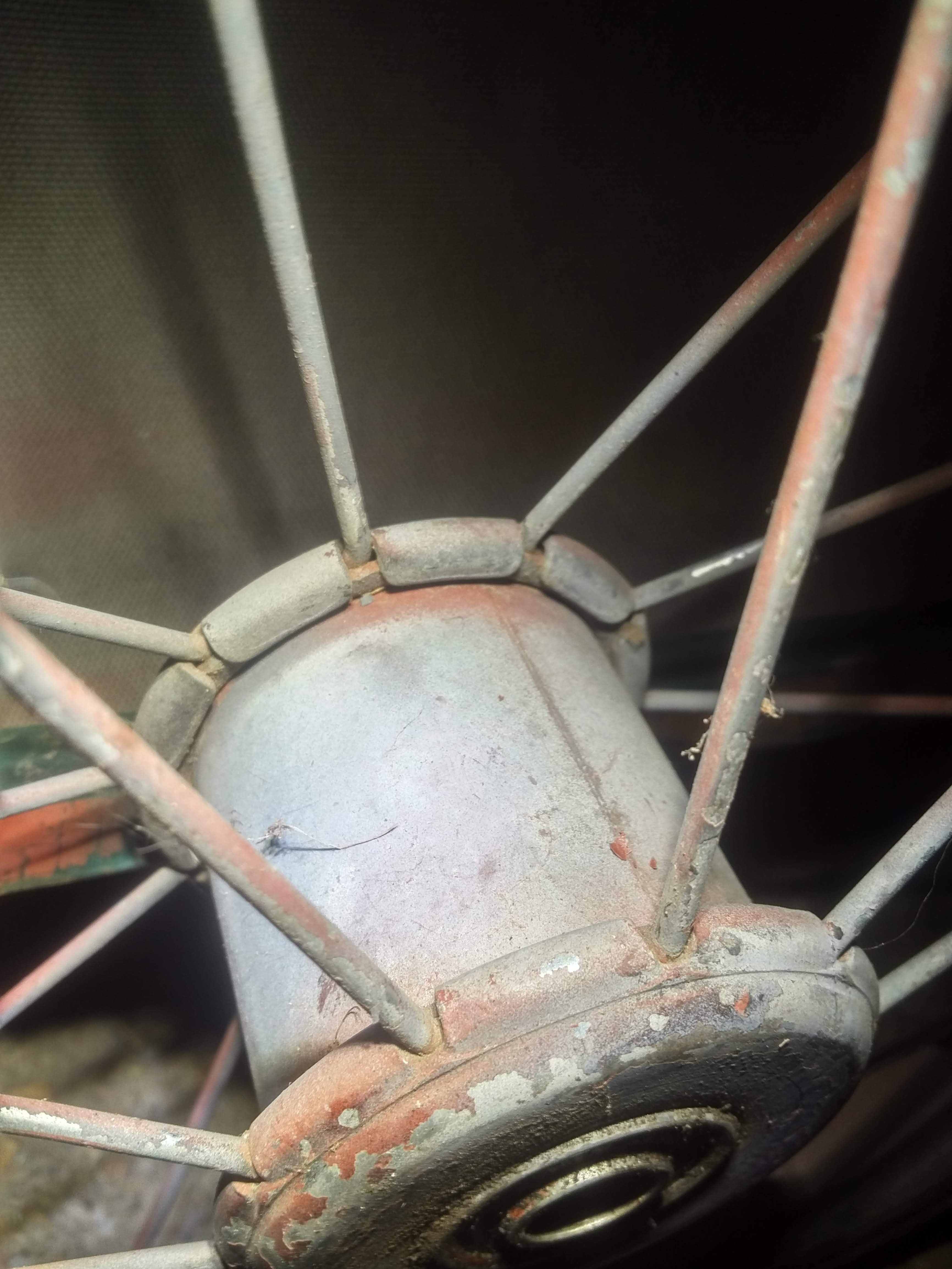
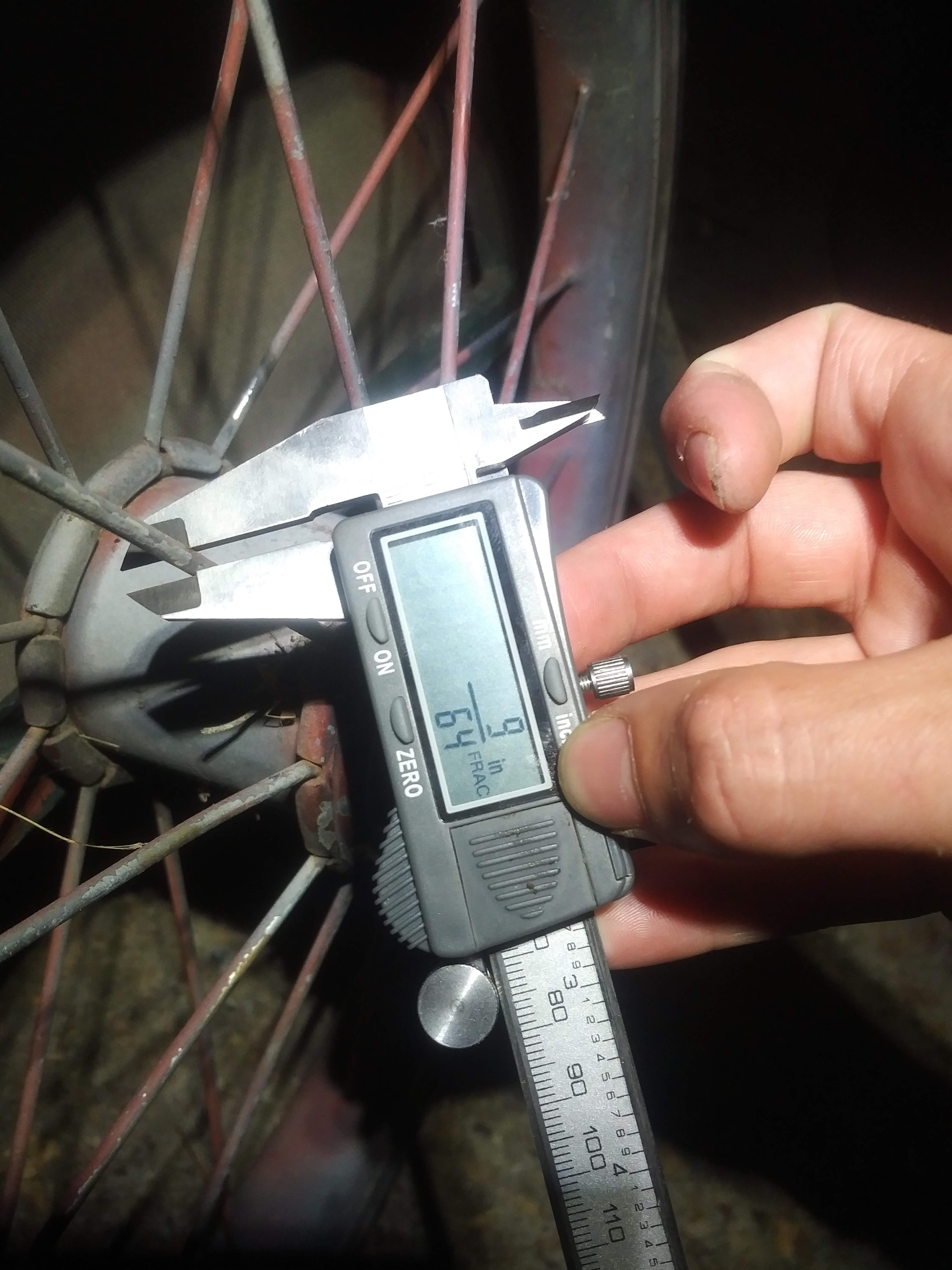
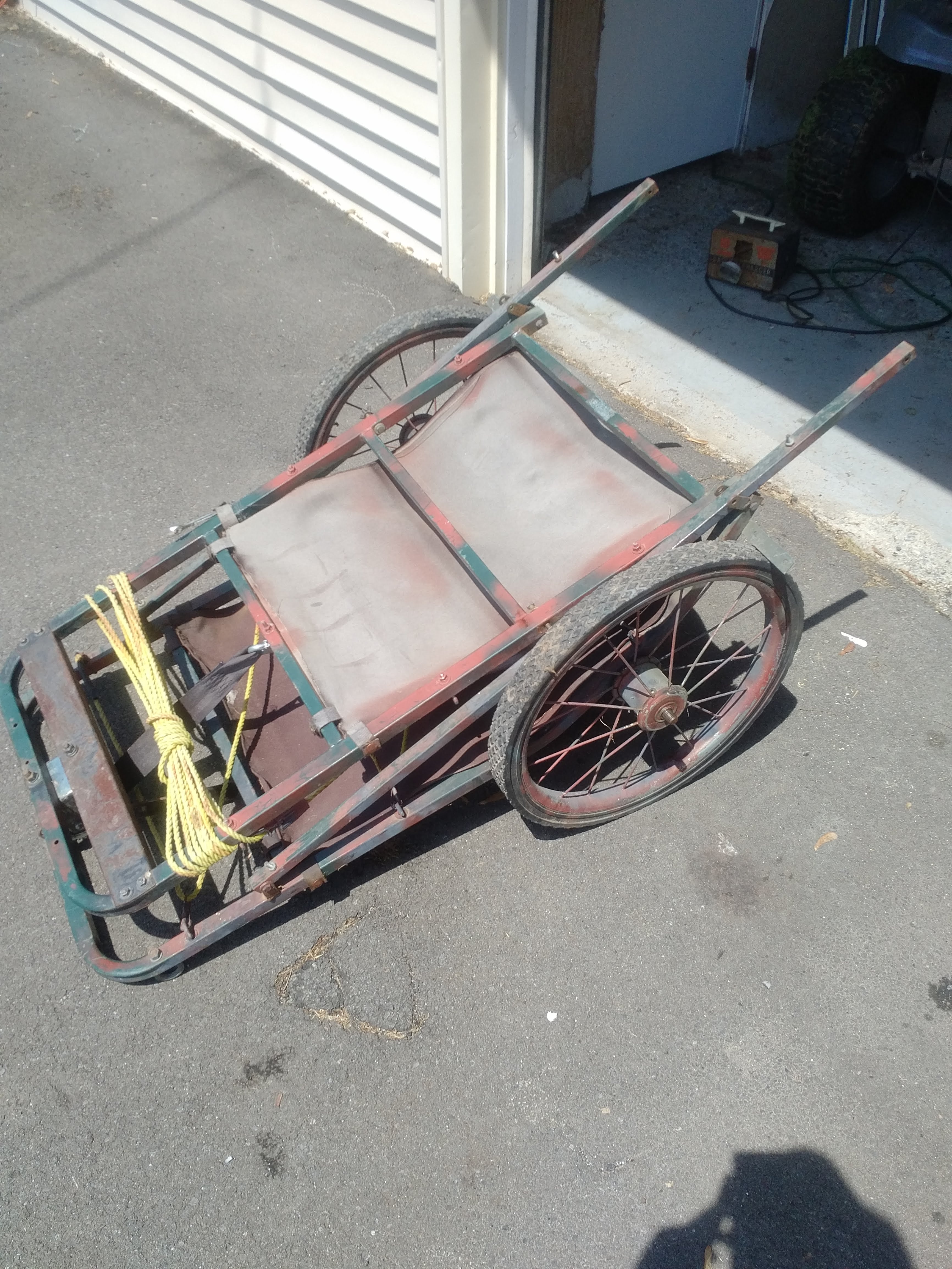
The other sprocket that I am unsure of how to mount is for the wheels. Although this kart does have a solid axle, it is not set up to spin. There are no bearings where the axle mounts to the frame of the kart. The wheels spin freely while the axle has a codder pin going through it to keep it stationary. The inner diameter of the wheel hub is round and does not have a cut out for a keyed shaft. Because of this, I decided it would be easiest to attach a sprocket to the hub of each wheel. Here is the 20" wheel/ tire that I am using.
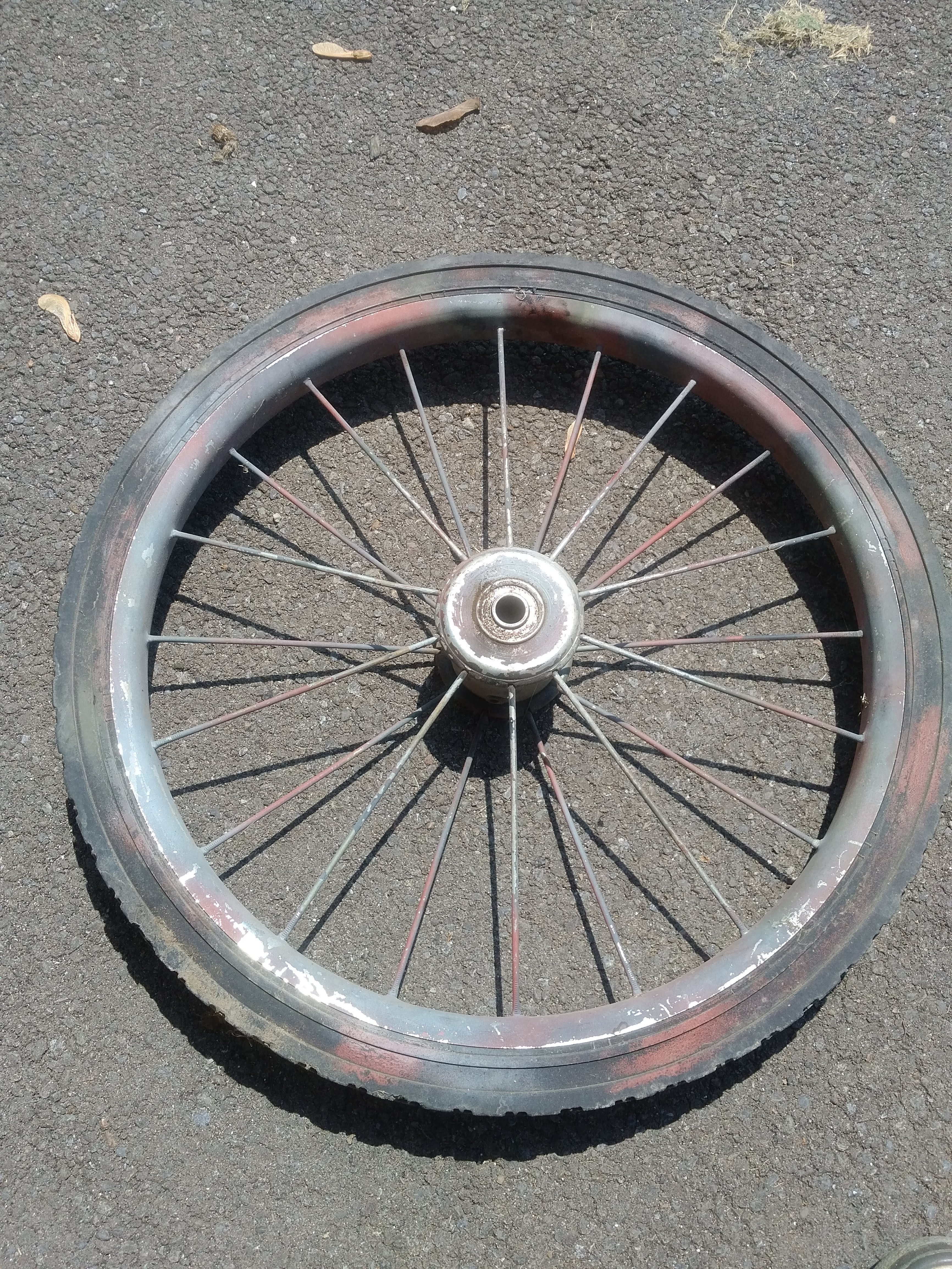
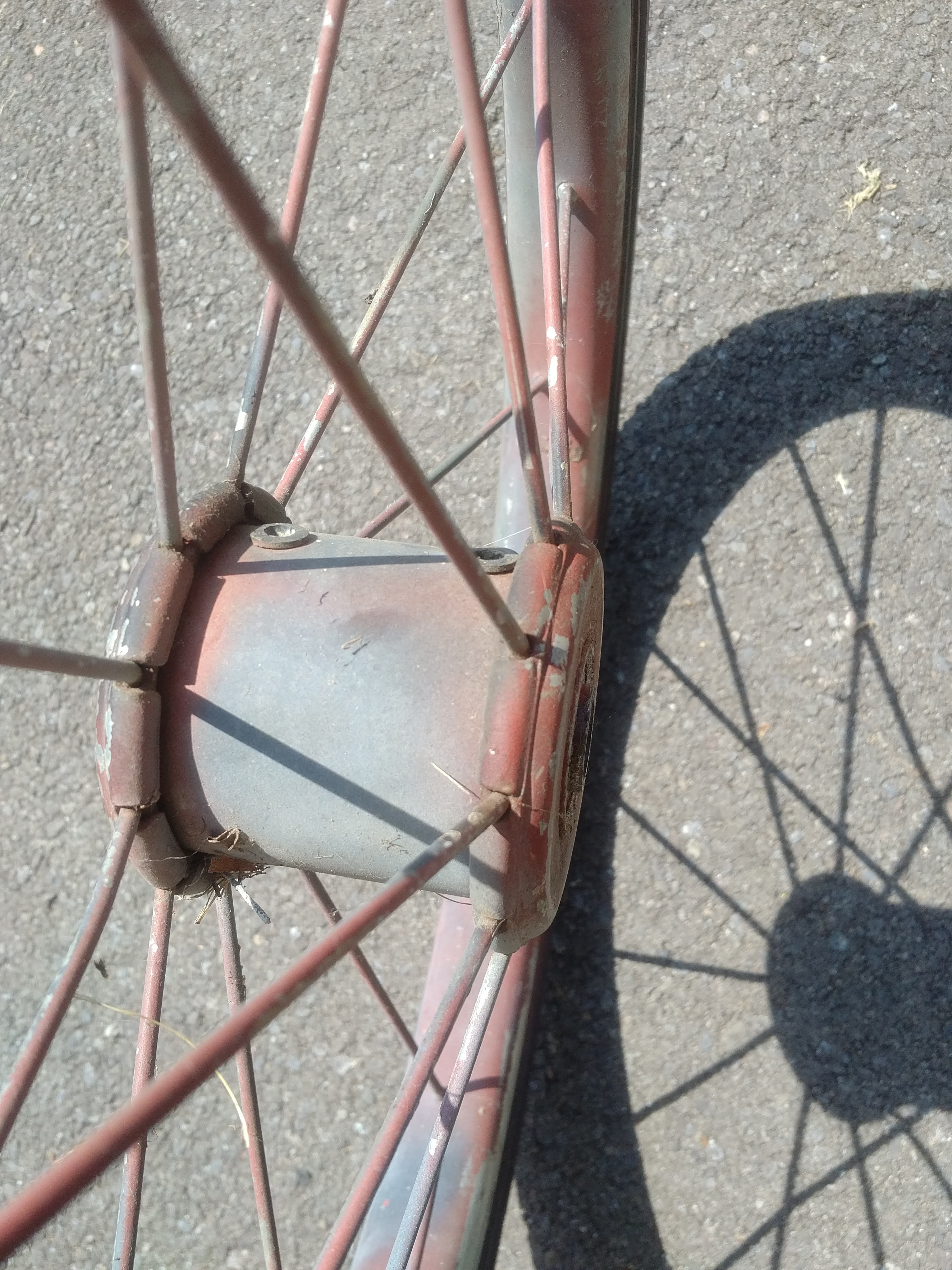
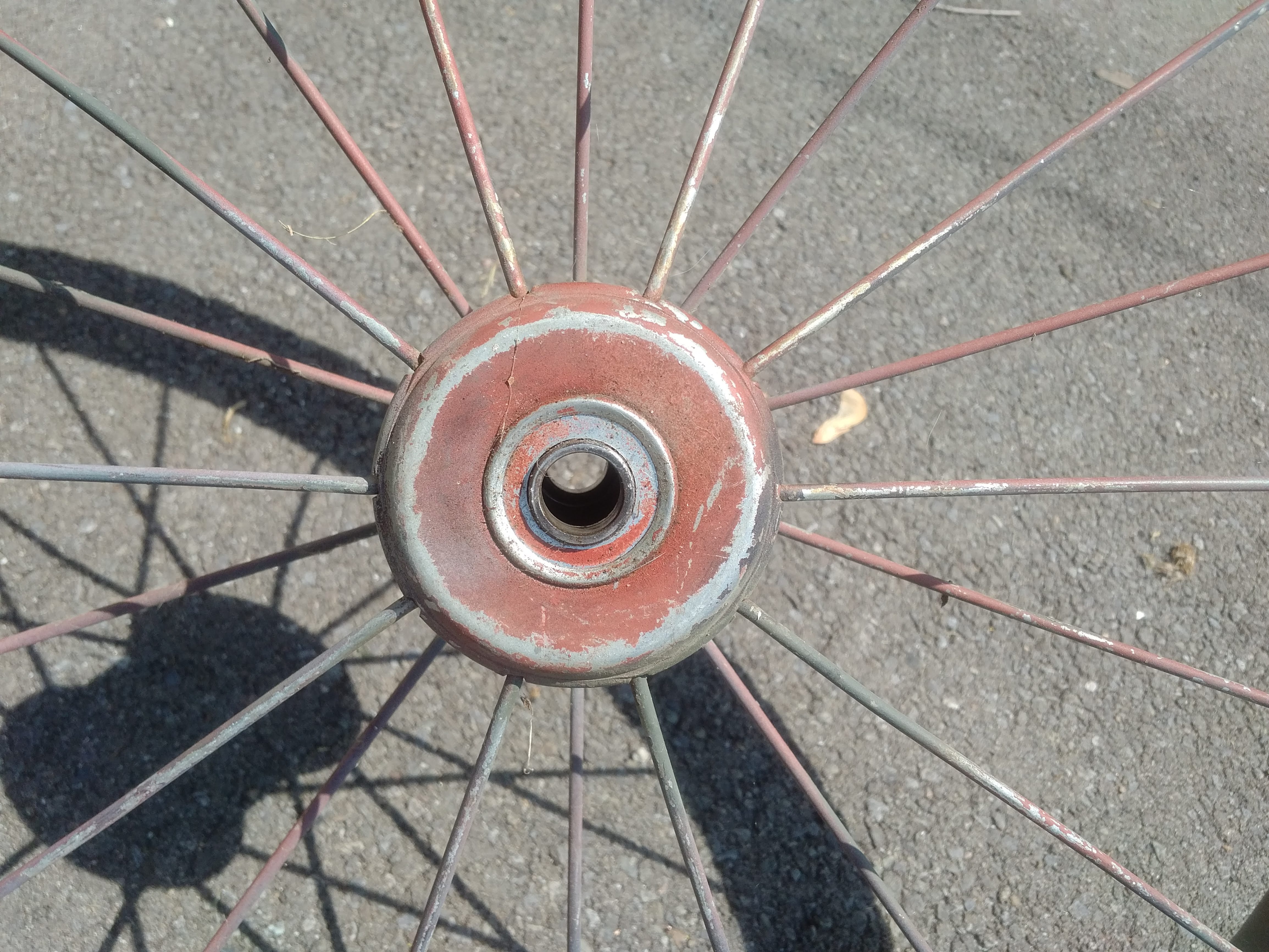
At first i was planning on drilling right through the sidewall of the wheel hub and bolting a flat style sprocket to the side of the wheel closest to the frame. But after some research I found out about clamshell, pineapple, and rag joint hub adapters. I've found that members on this forum use all different types of methods for attaching sprockets to wheel hubs. I am not entirely sure what is the best adapter for this build. Although the outer diameter of the wheel hub is round and doesn't taper, the spokes are not aligned in the pattern that most bicycle wheels are. They are spaced out much more and I don't really like the idea of clamping a mounting bracket that is going to put excessive stress on the spokes of the wheels. What do you guys think? Would my original plan of using bolts through the side of the hub to mount the sprocket work or should I consider purchasing some type of clamp for the outside of the hub?
Well its starting to get late here and i think I've made this post long enough. I am completely open to any suggestions or tips that you guys can give me. I will keep this thread updated as my work progresses on this build. thanks in advance to anyone willing to read all of this and provide advice.
The project I am currently working on is a motorized deer kart. I have a 24cc 2-stoke engine off of a stihl weed wacker. Although this is not a trike or tandem, i am hoping this is the right place to post this build. This project is not yet completed and I am posting it here to get some tips along the way. Here are some pictures of the cart itself
I got this kart off of craigslist for $40. Which I thought was a great deal. The kart is much more heavy duty than a lot of other ones I've seen. It also came with the hand crank winch attached which I thought was an awesome feature. I intend to have my chains and sprockets positioned so that I can still fold the kart up for transportation. I would like to use this kart for hauling deer out of the woods but it will probably be used more for hauling beer and gear in and out of camp.
The stihl trimmer was being thrown out so i grabbed it and got the engine running. The engine only needed a carb cleaning and a new primer bulb. I saved the engine, clutch housing, and throttle control with a kill switch. The rest of it I threw away. So all together I have about $45 into this. I am trying to keep this project as cheap as possible. I got some scrap angle iron for free that I am going to use for mounting the engine and creating a mounting bracket for the jackshaft. I also have some axles from a riding mower than I plan on using for the shaft of my jackshaft. But I know the sprockets, chains, pillow block bearings are going to be my main cost (none of which i have ordered as of 6/1/18). I have to include a jackshaft to get the gearing low enough. This cart only needs to go walking speed and not much faster than that. So here is a sketch up I did for the drivetrain and gearing plans.
I used a gearing calculator https://www.electricscooterparts.com/motor-jackshaft-wheel-gear-ratio.html to determine the sprocket sizes I will need to achieve a speed of about 3 MPH. The engine idles at 2800 rpm. So I assume the clutch will engage at 3000 rpm, or atleast close to it. If I use sprockets with 9 teeth to 72 teeth twice, clutch to jackshaft and then jackshaft to wheels, it will go about 2.8 MPH. Just slightly under the 3 MPH I was shooting for. I was able to find the owners manual online and that says the engine has a max of 7,700 RPM. So at 7,700 RPM it should be going about 7.18 MPH. Which is close to running speed. This comes out to be a 64:1 gear ratio. I figure this will give me a good range of speed all the way through the throttle. If someone knows of different gearing that would work better than please let me know.
One thing I'm not completely sure of is how I am going to attach the sprockets. First off is the clutch.
As you can see in the pictures, the clutch drum has a square hole. So I suppose I just need to find some steel rod that i can square off on my bench grinder and use a type B sprocket to attach it to the squared rod. This rod also has to be strong enough not to twist or bend when this kart has a deer on it and an engine spinning at 7,000 rpm. Which make me question if this is the way to go. If any of you guys have a better suggestion on how to attach the sprocket to the clutch, please let me know.
I also question if this clutch will be able to handle the load of this kart. I don't know for certain, but i don't think this kart will have much more than 150 lbs on it. Again, I'm sure someone on this forum has a lot more experience with these centrifugal clutches than I do. So if this clutch is just going to start slipping the minute I put some weight on it, than please let me know what modifications I can do to it or if I should look into something completely different.
The other sprocket that I am unsure of how to mount is for the wheels. Although this kart does have a solid axle, it is not set up to spin. There are no bearings where the axle mounts to the frame of the kart. The wheels spin freely while the axle has a codder pin going through it to keep it stationary. The inner diameter of the wheel hub is round and does not have a cut out for a keyed shaft. Because of this, I decided it would be easiest to attach a sprocket to the hub of each wheel. Here is the 20" wheel/ tire that I am using.
At first i was planning on drilling right through the sidewall of the wheel hub and bolting a flat style sprocket to the side of the wheel closest to the frame. But after some research I found out about clamshell, pineapple, and rag joint hub adapters. I've found that members on this forum use all different types of methods for attaching sprockets to wheel hubs. I am not entirely sure what is the best adapter for this build. Although the outer diameter of the wheel hub is round and doesn't taper, the spokes are not aligned in the pattern that most bicycle wheels are. They are spaced out much more and I don't really like the idea of clamping a mounting bracket that is going to put excessive stress on the spokes of the wheels. What do you guys think? Would my original plan of using bolts through the side of the hub to mount the sprocket work or should I consider purchasing some type of clamp for the outside of the hub?
Well its starting to get late here and i think I've made this post long enough. I am completely open to any suggestions or tips that you guys can give me. I will keep this thread updated as my work progresses on this build. thanks in advance to anyone willing to read all of this and provide advice.