
You are using an out of date browser. It may not display this or other websites correctly.
You should upgrade or use an alternative browser.
You should upgrade or use an alternative browser.
Art Fish Mobile Motor Bike prior Motor Bike DIY'er build to add side car maybe?
- Thread starter MEASURE TWICE
- Start date
MEASURE TWICE
Well-Known Member
Well I have it going, but I am going to revert back to regular belts on the pulleys. Section type belts around a small pulley seem not to have enough friction and I do have slippage on one pair of pulleys. I was able to go up a hill of about 10ft on a length of 50ft where I got a 100ft prior running start. The bike was about to stall (not engine stall) when pulley was slipping and engine was reving.
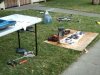
Soft sand I was trying to keep balance and think wise for a parade vehicle that would be off pavement I would add large 12 inch diameter inflatable bike wheels one each side as training wheels. A fish in the dust is one thing, a fish biting the dust is another")
One of the pairs of pulleys with a belt between dual jackshafts I may go with sprocket and chain.
MT
Soft sand I was trying to keep balance and think wise for a parade vehicle that would be off pavement I would add large 12 inch diameter inflatable bike wheels one each side as training wheels. A fish in the dust is one thing, a fish biting the dust is another
One of the pairs of pulleys with a belt between dual jackshafts I may go with sprocket and chain.
MT
MEASURE TWICE
Well-Known Member
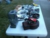
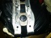
Motor when it was being revamped like 3yrs ago pics. Also when seeing how would fit the frame.
MT
MT
Attachments
MEASURE TWICE
Well-Known Member
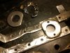
The one pillow bearing holder I needed to cut away the weld to its connection to the bottom dual jackshaft bracket took me a good 3 hours.
It is smooth enough cut away that now placing a new one in its place and just using two bolts where now the bracket it attaches to is to become slotted, will allow tensioning the belt that goes between top and bottom jackshafts.
There was just not enough tension I could adjust with the links by taking some out. At a point the belt just does not hold up and the links come apart. Maybe good for like car alternator without so much torque necessary so they probably would not slip there.
I'm going to pick up the 17.9 inch V-belt of the regular type tomorrow they ordered for me at the auto parts store.
If I can get ones that also fit the other 2 belts of the 3 total, I will switch from the section type belt and hope I get better friction and no slippage on the pulleys. I'd keep the section belts as a backup so I could get going in a pinch, but it probably will stay as a back up. They just don't have the grabbing power of a normal type v-belt, or at least I'm going to find out soon.
If anyone is interested in a neat mathematical constant used to find the length of belt or chain for use with pulleys or sprockets, when you only know the diameter of the pulleys or sprockets and their shaft bore size I can enlighten you.
It was from speaking with a person at Grainger that I found this out. Oh it probably is in a text book somewhere too! You have only a few steps using this way to get the answer, but it works as yesterday I measured the belt and verified it does work.
If I did it by trigonometry (Tangent = Opposite over Adjacent) and the equation (Circumference = 2 X [pie being 3.14] X Radius) it would have been way more steps.
I might see about getting a Basic Compiler and write a program to use this constant and get the answer in an instant. If by having a data base of available pulleys / belts and sprockets / chains one could be able to see what permutations could work. I could set it up to only get answers within a guard band.
You could just say also in this program I have this much available adjustment so you only find what would work and also be not right on the edge of working. In addition the chain or belt could be checked for availability, then it finds out whats in stock to be sold and your on your way building way quicker.
Additionally today I found out this about section belt measurements:
Finding the top outside of the section belt is also something I learning is not the same as putting a cloth tape measure over the top. The bumps from the links make it longer. I have to use a side profile an get the point on the belt that is even with the top edge of the pulley. It keeps going up and down like a saw tooth though. That means you have to go from point to point and not follow the bumps. On a length of about 18 inches you can have an error of more than 1 inch if not noting a section belt tricky way of measuring.
MT
Attachments
Last edited:
MEASURE TWICE
Well-Known Member
I got the Gates small length v-belt a regular type and I started on one left side of the jack shaft brackets mod to have just the bottom of the twin stacked jack shaft movable up and down for belt adjustment. The right side next.
I will also be welding a piece of metal on the adjacent side of both left and right brackets where I thinned out the width so that the pillow bearings do not rub on the brackets.
I have the top and the bottom of these four tower brackets attached so that they don't sway and are rigid.
I felt that if I slotted the metal as needed for adjustment, then about 2 inches length thinned 1/8 inch on the width and has been weakened to some degree so to beef it back up again I'll add some metal on the other side.
It will not interfere with anything and will fit OK. The rigidity of the 4 tower twin stacked jack shaft brackets shall not be compromised.
MT
Attachments
Last edited:
MEASURE TWICE
Well-Known Member
MEASURE TWICE
Well-Known Member
carb parts pictures disassembled and assembled:
http://outdoorpowerinfo.com/repairs/...o_lms_carb.asp
http://www.amazon.com/Briggs-Stratto.../dp/B0038U3I6C
Above are links to the carb that I have on my Briggs 80202 0430 3hp 4stroke side shaft engine.
It's not the carb that came with the engine as from the flea market it had no carb and I fixed up the engine and got this 498170 carb on Briggs and Stratton Engine.
It works fine and idles nice even without the governor on it. I would have kept the governor on it but the elbow 90 degree bend I used on the intake manifold made it a rather difficult task if I were to try. One thought was to use electronic sensors and servo motors to make the connection as they go around corners without bending.
Anyway what I did do was I put low throttle adjust and also high speed throttle adjust screws added to my carb linkages and it is working quite nice with the twist grip throttle.
Here is the problem if I can call it that. When I start the engine and it is idling nice and slow probably around 1750 rpm, the centrifugal clutch is doing fine being like in neutral and the bike does not need you to hold onto the brake levers when on level ground.
The clutch is supposed to be starting engaging at between 2000 rpm and at 2200 rpm be fully engaged which I suppose it does fine. The 1750 rpm idle speed is what the engine does when first starting the engine, but when you give it throttle to accelerate and maintain speed and then decide to come to a stop, it does not drop down to idle speed as fast as I would like.
I have stopped the bike and found after a second or so taking my hands off the hand brakes the motor bike is moving forward slowly as the idle is not dropped all the way down to its slowest speed like when I started the engine.
Note that the range of throttle position is fully at its minimum but needs as much as maybe 5 to 7 seconds when this happens if I don’t want the bike moving forward slowly.
This inexpensive carb has no low speed idle needle valve adjust or high speed needle valve adjust.
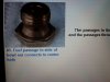
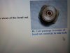
Inside the carb bowl is a part that serves as a nut to hold the bowl in place and also integral fuel passage way that I understand must do some kind of metering the fuel. You can see the picture in the attached link for the web page above for the #5 and #6 pictures.
Additionally there is picture #7 showing the main nozzle that goes up a center post to the venturi. That also must be metering the fuel as well.
If I knew if the main nozzle could be removed and replace with possibly a smaller one just enough to allow the carb with my engine to return to idle that much quicker from an above idle speed, I think I would like to try that.
I hope it would not have too much adverse effect on the range of speed up to max throttle as it is now. I think it would to some degree also make high speed max somewhat lower but not that much and I think that would be OK.
Only other way not needing very much in specialized parts or tools would be if I made a copper sheet cut out and put it where the gasket goes either right at the engine intake or between the carb and the intake manifold elbow. The part would include a second gasket so it would not leak and also make the diameter of the intake slightly smaller.
The smaller amount of volume of fuel air mixture would maybe equate to a lower idle if it does not stall it out all together.
I think this would be easiest, but if for this carb I could find a main nozzle that fits and can be installed with original removed without too much cost and specialized tool cost I could go that route as well.
Any help with this kind of thing?
I know cars with automatic transmissions have this happening all the time it seems as people keep inching up when the take their foot off the brake when at a stop light, right?
MT
PS:
I looked at other stuff online and hear press fit jets and nozzles may be removed with drift punch.
There also may be a washer or something and something else whatever that is which covers the jet or nozzle and you remove that first. Punching it through with a press or soft mallet carefully and it comes out the other side hopefully in one piece and could be reused later if not damaged.
Then a new part with different size can be reinstalled. More detailed info for my specific carb, the guy from Briggs on the phone discouraged any changing or working on jet parts and was no help other than saying it should work with my engine.
It does quite well, but the drop down to idle takes too long.
The original carb is a vacu-jet carb and uses jets that are with a screwdriver slot and screw threads. I have cleaned them quite easily. I have hear of using wood tooth pick so not to scratch parts and recently sounds good too, using monofilament fishing line.
Last I think maybe the use of the elbow 90 degree bend to fit carb to engine in tight fit on frame may be having effect on the slow response to going back to idle speed? It came off a lawn mower that really does not need any quick response to get back to idle. I'll check with others that extended the intake, especially if on a Briggs engine like mine. I know I have seen them on this site.
http://outdoorpowerinfo.com/repairs/...o_lms_carb.asp
http://www.amazon.com/Briggs-Stratto.../dp/B0038U3I6C
Above are links to the carb that I have on my Briggs 80202 0430 3hp 4stroke side shaft engine.
It's not the carb that came with the engine as from the flea market it had no carb and I fixed up the engine and got this 498170 carb on Briggs and Stratton Engine.
It works fine and idles nice even without the governor on it. I would have kept the governor on it but the elbow 90 degree bend I used on the intake manifold made it a rather difficult task if I were to try. One thought was to use electronic sensors and servo motors to make the connection as they go around corners without bending.
Anyway what I did do was I put low throttle adjust and also high speed throttle adjust screws added to my carb linkages and it is working quite nice with the twist grip throttle.
Here is the problem if I can call it that. When I start the engine and it is idling nice and slow probably around 1750 rpm, the centrifugal clutch is doing fine being like in neutral and the bike does not need you to hold onto the brake levers when on level ground.
The clutch is supposed to be starting engaging at between 2000 rpm and at 2200 rpm be fully engaged which I suppose it does fine. The 1750 rpm idle speed is what the engine does when first starting the engine, but when you give it throttle to accelerate and maintain speed and then decide to come to a stop, it does not drop down to idle speed as fast as I would like.
I have stopped the bike and found after a second or so taking my hands off the hand brakes the motor bike is moving forward slowly as the idle is not dropped all the way down to its slowest speed like when I started the engine.
Note that the range of throttle position is fully at its minimum but needs as much as maybe 5 to 7 seconds when this happens if I don’t want the bike moving forward slowly.
This inexpensive carb has no low speed idle needle valve adjust or high speed needle valve adjust.
Inside the carb bowl is a part that serves as a nut to hold the bowl in place and also integral fuel passage way that I understand must do some kind of metering the fuel. You can see the picture in the attached link for the web page above for the #5 and #6 pictures.
Additionally there is picture #7 showing the main nozzle that goes up a center post to the venturi. That also must be metering the fuel as well.
If I knew if the main nozzle could be removed and replace with possibly a smaller one just enough to allow the carb with my engine to return to idle that much quicker from an above idle speed, I think I would like to try that.
I hope it would not have too much adverse effect on the range of speed up to max throttle as it is now. I think it would to some degree also make high speed max somewhat lower but not that much and I think that would be OK.
Only other way not needing very much in specialized parts or tools would be if I made a copper sheet cut out and put it where the gasket goes either right at the engine intake or between the carb and the intake manifold elbow. The part would include a second gasket so it would not leak and also make the diameter of the intake slightly smaller.
The smaller amount of volume of fuel air mixture would maybe equate to a lower idle if it does not stall it out all together.
I think this would be easiest, but if for this carb I could find a main nozzle that fits and can be installed with original removed without too much cost and specialized tool cost I could go that route as well.
Any help with this kind of thing?
I know cars with automatic transmissions have this happening all the time it seems as people keep inching up when the take their foot off the brake when at a stop light, right?
MT
PS:
I looked at other stuff online and hear press fit jets and nozzles may be removed with drift punch.
There also may be a washer or something and something else whatever that is which covers the jet or nozzle and you remove that first. Punching it through with a press or soft mallet carefully and it comes out the other side hopefully in one piece and could be reused later if not damaged.
Then a new part with different size can be reinstalled. More detailed info for my specific carb, the guy from Briggs on the phone discouraged any changing or working on jet parts and was no help other than saying it should work with my engine.
It does quite well, but the drop down to idle takes too long.
The original carb is a vacu-jet carb and uses jets that are with a screwdriver slot and screw threads. I have cleaned them quite easily. I have hear of using wood tooth pick so not to scratch parts and recently sounds good too, using monofilament fishing line.
Last I think maybe the use of the elbow 90 degree bend to fit carb to engine in tight fit on frame may be having effect on the slow response to going back to idle speed? It came off a lawn mower that really does not need any quick response to get back to idle. I'll check with others that extended the intake, especially if on a Briggs engine like mine. I know I have seen them on this site.
Last edited by a moderator:
MEASURE TWICE
Well-Known Member
Going to check for air leaks on intake parts: the elbow manifold, 15 degree tilt adapter plate, and the carb using some WD40 spray.
I'll make better gaskets or use some high temp rtv forma-gasket stuff if there are leaks causing drop down to idle speed taking too long.
MT
I'll make better gaskets or use some high temp rtv forma-gasket stuff if there are leaks causing drop down to idle speed taking too long.
MT
MEASURE TWICE
Well-Known Member
I saw some information on using a drift punch and a press.
The carb has to have a space for the jet to come out the opposite side or it is press fit and non-removable as any other way to do may damage the carb body or cannot be done at all.
I have my idle drop too slowly when I throttle up and then go back to throttle at idle. This slow drop back to idle speed in conjunction with a centrifugal clutch makes the bike move very slowly for about 5 seconds if I don't hold the brakes.
Annoying, but I hear it could be air leak at intake connections and am going to try spray WD40 while idle or at speed to see if there is any change in how it runs. It’s not a fix in itself, just tells you if there is a leak and then I re-gasket.
The re-jetting I think is not a fix for this, but was looking at all possibilities. Actually what I was looking at on my carb without any needle valves (cheap) was a fuel nozzle. I'll leave it be. Some day this other part which is an integral fastener nut / jet that holds the bowl in place I may solder over and re-drill smaller.
Picture #5 an #6 show the integral fastener nut / jet
Picture #7 is the main nozzle into venturi
http://outdoorpowerinfo.com/repairs/briggs_walbro_lms_carb.asp
Fuel at near the bottom of the bowl goes from a point on the side of this integral fastener nut / jet. Then it connect in the center of the integral fastener nut / jet and goes up into the space directly above where it is threaded into. This is where it meets the main nozzle into venturi and that is what I can tell from the pictures I found for my carb.
If I were to make the integral fastener nut / jet smaller by soldering over just one or the other orifices in it and re-drill smaller I may try that, but will definitely try this as a last resort.
MT
Attachments
Last edited:
I think you should forget about the prejetted carb and get one like this. It has the small ideal jet on the side and you can see the high speed needle on the bottom of the carb they are used on 5& 7 HP Tecumesh snowblowers. They should be easy to find used...........Curt http://www.alamia.us/Tecumseh_Carburetor_632615_p/rott-13147.htm
MEASURE TWICE
Well-Known Member
Thanks CF for that, but I am sticking with this cheap carburetor as I just thought the problem may even not be leaking air at the intake or need a carburetor with idle adjustment and fuel mixture ratio.
It was what I had seen when I had found slipping of 1 belt between the top and bottom twin stacked jackshafts that got me thinking.
Finally it all jived.
I know that those toy cars that you push a few times the wheels and then you hear all those gears spinning. The thing just has a weight and a very low gear ratio. You set the car down and it goes for a while by the weight like a flywheel and it is spinning fast.
Here is what is going to fix the problem I think. As I am already fixing the slipping belt as planned by slotted the bottom jackshaft, that allows tension to be set between the bottom and top jack shaft pulleys, then the problem will most likely go away.
Here is why. When I ran this same carburetor on the engine but with an 8:1 ratio it was too high a gear ratio and the clutch itself had a time getting the shoes to grab until the bike got up the 15mph. When I ran it that way with 1 jackshaft I did not have the problem of idle not dropping fast enough.
That means at least at one time that engine and carburetor did not have the problem and gives me hope it is not a problem with either of those two parts.
I wanted to go less than 5 mph without pulsing the throttle. Less than 5mph for parade speed. Then the answer was to make it a 40:1 ratio. I've done that and it works great, except for 1 of the 3 belts slips on a small 2 inch diameter pulley on the top jackshaft.
When I take the bike with throttle up to speed and then return to idle speed on the twist grip, the butter fly valve closes the carb throat and the engine attempts to slow.
The motor bike has its own momentum and transfers that movement from the rear wheel to a belt to the bottom jackshaft. That bottom jackshaft slips on the belt that connects to the top jack shaft and so applying the brakes does not fully continue the path from the top jackshaft to the centrifugal clutch bell.
If it did not slip it would continue the path to the centrifugal clutch bell and slow the engine very rapidly as I brake the bike to a stop. The shoes on the centrifugal clutch would disengage and I would have the engine fully at idle and not have to hold the brakes to keep the motor bike from inching forward slowly.
What happens when it slips is that there is not much force to slow the engine. In addition the large 1st pulley 10 inch diameter and the jackshaft it is on as well as the 2nd pulley on that jackshaft have mass and add to the momentum the engine already has. Basically a second flywheel effect is what I have.
The belt slips ever so much more if I come to an abrupt stop as opposed to braking to a stop slowly. Slowly stopping I don’t notice this slow inching forward of the bike nearly at all. Then in the case that all belts are able to act properly and slow the engine as the bike slows the problem should be solved.
This of course is only up to the point at which the speed of the bell is somewhere under 2200 rpm. 2000 rpm to 2200 rpm is the range from which bell on the centrifugal starts to have shoes ting the bell and then the shoes fully engage the bell.
Since I have to check this idea out in reality, for now it is just a hypostasis.
If it does what I think, I will not have slipping of the belts as I accelerate with throttle up on level ground or up inclines. When going down inclines with throttle down at idle I can use the engine as a brake effectively and that can save on brake shoes, but obviously not gas.
I was in an old two stroke car that had a manual shift. The engine would act as a brake while in gear with the throttle down, unless you use the optional roll fast engaged. Maybe I can add another clutch to act as roll fast did in this vehicle to save on gas. It is just the 40:1 ratio is a gas hog no matter what!
Tune in next time for the exciting adventure of “is it real” 40:1.
MT
Last edited:
MEASURE TWICE
Well-Known Member
I have not yet had time yet to check my bike out and the issue I thought I had with the carburetor. I did however look at the videos of past where recorded how it acted as though the carburetor was maybe to blame.
It seems to be just the additional momentum from all the jackshafts and pulleys going that if one belt slips half way through the drive-train you have this effect of the engine continuing to be going above idle although the throttle is all the way down. Then additionally you can have a delay of dropping to idle speed. Then you have the bike creeping forward slowly after you have just let go of the brakes from a complete stop.
A particular clip in a video was where I came to a slow stop. The slow stop as I deduced made it such that little slipping of that one belt in the middle of the drive-train was happening or none at all. When after I let go of the brakes which was a second or less after stopping completely, there was none of the bike trying to creep forward.
In stark contrast, right after I did the above stop I gave full throttle a couple of times with one of the V-brakes applied and then let go of the brake. I went forward about 2 feet and then grabbed both brakes for just a second. Then when I let go of the brakes the engine was still revving and I inched forward a bit and applied the brakes again and after 2 seconds of that released them and there was no forward creeping.
Then the engine had slowed enough and the clutch had disengaged the shoes from the bell. This slipping of the one belt happened to be more so when I accelerated quickly and was holding the brakes. Sort of a no brainer. Maybe later it will be over powering the brakes with out the belt slipping?
The slipping of the belt allows half the drive train to act as a second big flywheel and keeps the engine up at a speed faster than idle and has the clutch shoes engaging the bell. This is definitely not ideal!
I already knew I was not going to allow that belt to continue slipping as I intend to move through deep sand or silt slowly. This is to be so, even if I have to have training wheels on the rear. I could even better yet have both front and rear training wheels attached. All of this at less than 5mph but with enough torque to do so!
At higher speeds without a fish art mobile covering a hill climber of a motor bike will be had when all belts grab sufficiently.
There will not be any more of this slow creeping forward after a stop. I have to see about the V-brakes reacting to not just the total weight of the vehicle, but the extra added rotational weight of the transmission 40:1 ratio.
I guess I did not have my mind fully evaluating what I observed when I took videos of the bike first using the 40:1 ratio twin stacked jackshafts. I was really concerned about fixing the slipping belt, but had not thought about the two things combined, slipping of 1 belt and an extra flywheel effect!
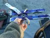
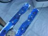
The fish covering I started with the 6ea welded to frame threaded mounts to add the fish skeleton frame. Part of the fish skeleton frame is complements of a thrash picked glass table frame. The frame parts have a nice fish body shape and also a tail as well. The hollow steel tubes are already painted and I only will sand the paint off to near where I will weld something to have it attach to the motor bike frame threaded points I already have finished.
I’m so glad I rewinded a few tapes to view and see what I was encountering so that I can move forward with the fish mobile art cover for the motor bike!
MT
It seems to be just the additional momentum from all the jackshafts and pulleys going that if one belt slips half way through the drive-train you have this effect of the engine continuing to be going above idle although the throttle is all the way down. Then additionally you can have a delay of dropping to idle speed. Then you have the bike creeping forward slowly after you have just let go of the brakes from a complete stop.
A particular clip in a video was where I came to a slow stop. The slow stop as I deduced made it such that little slipping of that one belt in the middle of the drive-train was happening or none at all. When after I let go of the brakes which was a second or less after stopping completely, there was none of the bike trying to creep forward.
In stark contrast, right after I did the above stop I gave full throttle a couple of times with one of the V-brakes applied and then let go of the brake. I went forward about 2 feet and then grabbed both brakes for just a second. Then when I let go of the brakes the engine was still revving and I inched forward a bit and applied the brakes again and after 2 seconds of that released them and there was no forward creeping.
Then the engine had slowed enough and the clutch had disengaged the shoes from the bell. This slipping of the one belt happened to be more so when I accelerated quickly and was holding the brakes. Sort of a no brainer. Maybe later it will be over powering the brakes with out the belt slipping?
The slipping of the belt allows half the drive train to act as a second big flywheel and keeps the engine up at a speed faster than idle and has the clutch shoes engaging the bell. This is definitely not ideal!
I already knew I was not going to allow that belt to continue slipping as I intend to move through deep sand or silt slowly. This is to be so, even if I have to have training wheels on the rear. I could even better yet have both front and rear training wheels attached. All of this at less than 5mph but with enough torque to do so!
At higher speeds without a fish art mobile covering a hill climber of a motor bike will be had when all belts grab sufficiently.
There will not be any more of this slow creeping forward after a stop. I have to see about the V-brakes reacting to not just the total weight of the vehicle, but the extra added rotational weight of the transmission 40:1 ratio.
I guess I did not have my mind fully evaluating what I observed when I took videos of the bike first using the 40:1 ratio twin stacked jackshafts. I was really concerned about fixing the slipping belt, but had not thought about the two things combined, slipping of 1 belt and an extra flywheel effect!
The fish covering I started with the 6ea welded to frame threaded mounts to add the fish skeleton frame. Part of the fish skeleton frame is complements of a thrash picked glass table frame. The frame parts have a nice fish body shape and also a tail as well. The hollow steel tubes are already painted and I only will sand the paint off to near where I will weld something to have it attach to the motor bike frame threaded points I already have finished.
I’m so glad I rewinded a few tapes to view and see what I was encountering so that I can move forward with the fish mobile art cover for the motor bike!
MT
Last edited:
MEASURE TWICE
Well-Known Member
See page #6 post #51
http://motorbicycling.com/showthread.php?t=29678&page=6
See page #5 post #41
http://motorbicycling.com/showthread.php?t=29678&page=5
This is where there are 5 pictures of what I did to have so far a way to make the motor bike multi-purpose.
Fish covering depiction on page 5.
It will be modular so that the fish skeleton frame can be added and removed. The fish skeleton frame will be covered with fire proof sprayed fabric that looks like the California Sheeps Head Fish skin.
Later the whole thing will be crawling across the desert in search of crill
MT
Last edited:
MEASURE TWICE
Well-Known Member
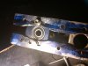
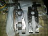
The twin stacked jackshaft brackets with added welded on metal to sides of where slots for bottom jackshaft made adjustable pictured.
The sides of angle bracket got thin where slot is for adjustment. The thinned area is also on the non-adjustable top jack shaft as well so pillow bearings fit in place, but a longer length of metal thinning on the bottom adjustable one would have otherwise been unacceptable without adding some more metal to opposite side.
MT
Attachments
killercanuck
New Member
Sounds like your getting her nicely dialed in. Better to have a solid base set before starting the covering, so you don't have to pull that off to work on something you forgot, heh heh.
MEASURE TWICE
Well-Known Member
Thanks, KC
I had the twin jackshafts brackets back on with the adjustable height for the bottom jackshaft. This worked very nicely as I was able to get the 2” pulley with the regular vee-belt so it would not slip at all.
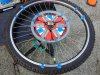
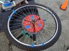
I went on to the rear drive belt and had added an adjustable diameter pulley so that belt there also can be adjusted. I just over did it and guess it was late and with little light, it was too late till I heard a crack. The rear washing machine pulley I mounted to the spokes bent and cracked. No damage to anything but the pulley was seen bent and light showing through a ½ long crack along the edge.
I have another same washing machine pulley I will get to attach with all of the reusable parts I already made to attach it to the spokes with.
Sort of a bummer in some ways, but I did get on the right track a bit anyway. I will be a while again to replace the broken part with a spare. I have to grind with Dremel and drill holes for screws. I also have to bend carefully the tabs to get the slight cone shape of the spokes compensated for.
Well now I learned. Get a flash light atop my head to look with plenty of light when it is dark.
Go small steps with tightening! Anyway I have a feel for it now. The pulleys on the jackshafts are much more sturdy and can have more stress, but not the 10inch spoked pulleys. I have one on the rear wheel and another is the first pulley that attaches to the centrifugal clutch.
Not that I won’t get by with making my own rear wheel drive with what I have, but are the remakes of what was the whizzer sheave made today of aluminum or stainless steel?
If it is stainless steel, I think for strength I could maybe shell out some bucks. All the parts thyat attach the sheave and the sheave itself were I think like $140. There was an option to already have it mounted on a wheel with coaster brake for maybe $170. You use your own tire and tube I think, but can’t recall exactly. Clearance for it to fit my bike I have to check on and I can’t use the coaster brake as I have no pedals, just pegs.
I had checked and there was some question as to would the clamps to attach the sheave work with the spoke pattern on the wheel I intend to use.
MT
I had the twin jackshafts brackets back on with the adjustable height for the bottom jackshaft. This worked very nicely as I was able to get the 2” pulley with the regular vee-belt so it would not slip at all.
I went on to the rear drive belt and had added an adjustable diameter pulley so that belt there also can be adjusted. I just over did it and guess it was late and with little light, it was too late till I heard a crack. The rear washing machine pulley I mounted to the spokes bent and cracked. No damage to anything but the pulley was seen bent and light showing through a ½ long crack along the edge.
I have another same washing machine pulley I will get to attach with all of the reusable parts I already made to attach it to the spokes with.
Sort of a bummer in some ways, but I did get on the right track a bit anyway. I will be a while again to replace the broken part with a spare. I have to grind with Dremel and drill holes for screws. I also have to bend carefully the tabs to get the slight cone shape of the spokes compensated for.
Well now I learned. Get a flash light atop my head to look with plenty of light when it is dark.
Go small steps with tightening! Anyway I have a feel for it now. The pulleys on the jackshafts are much more sturdy and can have more stress, but not the 10inch spoked pulleys. I have one on the rear wheel and another is the first pulley that attaches to the centrifugal clutch.
Not that I won’t get by with making my own rear wheel drive with what I have, but are the remakes of what was the whizzer sheave made today of aluminum or stainless steel?
If it is stainless steel, I think for strength I could maybe shell out some bucks. All the parts thyat attach the sheave and the sheave itself were I think like $140. There was an option to already have it mounted on a wheel with coaster brake for maybe $170. You use your own tire and tube I think, but can’t recall exactly. Clearance for it to fit my bike I have to check on and I can’t use the coaster brake as I have no pedals, just pegs.
I had checked and there was some question as to would the clamps to attach the sheave work with the spoke pattern on the wheel I intend to use.
MT
Last edited:
MEASURE TWICE
Well-Known Member
http://www.ebay.com/itm/Rear-Transm...pt=Motorcycles_Parts_Accessories&vxp=mtr#shId
http://www.ebay.com/itm/Rear-Wheel-...Parts_Accessories&vxp=mtr&hash=item335b17ad40
Saw this knock off of a Whizzer rear sheave with included mounting hardware. It was saying $39 and $24 shipping from Taiwan to United States where I am. Not sure it can fit my wheel, but they also have for $90 a wheel 26 inch that has the sheave and $56 to ship to USA.
Last time I called Whizzer or whoever they are now and really do legally have the rights to use the name, they did not have just the sheave and mounting hardware for the 26 inch wheel. They said they were sold out of them. Whole bikes were available but not just parts. Maybe I will try contacting them again. I really would rather buy from a retailer within the USA.
MT
I found this again:
http://whizzermotorbike.com/
http://whizzermotorbike.catalog.com/browseGroup.cfm?item_group_id=48792
32/34 Bracket & 2 Screws-Belt Sheave (9 sets necessary) N-3018 $5.15
33 Sheave - (Does not include brackets & screws) 2973 $27.85
Looks like (9 * $5.15 = $46.35) + (1 * $27.85) = $74.20 to get this if it can fit my 26" wheel. They use a cogged AX belt, but I have the belt I would get myself. Shipping extra to see what that would be.
Still the web site says they are out of the sheave, but have the mounting hardware. I will call again and see if there is a waiting list.
Last edited:
MEASURE TWICE
Well-Known Member
http://motorbicycling.com/showthread.php?t=17596
This has the info I remembered by Gunther's Thread. Spoke size needs to be right and 36 spokes. Already I know I have too thin spokes this and cost to get the whole wheel if it could be made with a hub with out gear and foot brakes I'm not sure the cost for me would make sense. I can check back with Memory Lane Classics in Ohio again. They did answer question on the phone and were quite nice!
http://www.memorylane-classics.com/Whizzer Parts/Whizzer Rim Parts.htm
Stainless Steel Sheave they show:
236 Sheave Rear Wheel Stainless Steel $95.00
w-74 Sheave Spacers (Set of 9) $32.00
$127.00 seems it would be plus shipping and I would have to have the right size spokes.
This would be real nice though!
MT
Last edited:
MEASURE TWICE
Well-Known Member
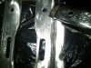
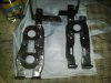
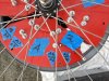
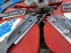
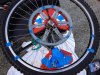
I made some headway removing my cracked rear drive pulley and labeling the parts so after getting my spare pulley drilled to fit and removed necessary metal to allow the tabs to line up, it will go together right.
The tabs I speak of are what remain after cutting off center of spoked pulley bore of a regular washing machine pulley.
A bike wheel has a slight cone shape to the total of all spoke combined, so this has to be taken into account.
A rag joint mount is closer to the hub so, I guess they just don't have as much of this angle. My type of rear drive pulley mount covers enough area going toward the rim that I make this cone shape allowance by compensating for the shape of the pulley tabs angle.
This makes it so the pulley grasps the spokes on the 26 inch rear wheel and does not distort. The spokes are sandwiched in between plywood covered resorcinol glue and epoxy paint.
There are 8 stainless steel screws, flat washer of various sizes, split lock washers, regular nuts, and nylon locking nuts that have to go on with additional shims. I labeled very meticulously everything to be sure it goes back right.
MT
Note: Center photo is with the split lock washers and nylon insert locking nuts already removed and am ready to finish removing the 8 screws on 1/3 of my pulley non-rag-joint type pulley to spokes attachment.
Attachments
Last edited:
MEASURE TWICE
Well-Known Member
In reference to post #134 page #14 of Dracothered's thread:
58s Schwinn Wasp Build (My Dad's old bike)
http://motorbicycling.com/showthread.php?p=449185#post449185
===============
I should clarify that the force that could pull the axle on the rear, out of the dropouts may be the belt stretch pulling back, not the engine torque. This would only be if the nuts loosen.
I have to see the amount I need to tension the belts what would be the minimum so I would not have slippage and lessen bearings wearing out quicker.
The first and easiest way for building a device to tension the belt in the rear dropouts, is a tool I would temporarily attach. This would not be something always needed for every ride, so just having the tool handy would do.
The spreading of the rear dropouts by placing a spacer on just the left side to fit my drive pulley, I shall check to see if it caused much shortening of that left side’s dropout. If it did shorten one side, then maybe that is why I am adjusting the wheel so the tire does not rub.
Another reason may be to clear the drive pulley I may not have spaced it enough and so it is compensated for by being at an angle.
I’ll take a look at it when I get back to working on it again.
MT
Last edited: