Stumped on Friction Drive

GoldenMotor.com

bean4life32

New Member
Feb 21, 2009
8
0
0
Pacific Northwest
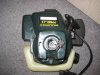
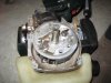
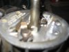
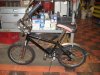
i am finally stumped. I have a 25cc craftsman weed wacker engine (no clutch) and I am trying to figure out how to adapt a friction drive to it, the only way to connect to the drive shaft is the square insert. I was wondering if there was anyone who could put in their two cents for ideas on how to adapt a friction drive to that without welding the drive directly onto the drive shaft (so i can change pegs, polyurethane wheels, wood wheels, etc...)?

I know people have had this problem so i was wondering on getting some tips on home to adapt the wacker to be a friction drive and what others have done

(Other than welding, have thought of using the cable from the drive part of the wacker, tapping the square insert so that i can put a screw right into the drive???)

I am new to this forum and was referred here so if anyone can help that would be great thanks.
 

Attachments

a_dam

New Member
Feb 21, 2009
351
0
0
Momence, IL
I'm not familiar with the weed-wacker motor shafts yet. Could you describe it more, or better yet, get more pics of the actual motor shaft end? Were you planning on keeping the pullstart and plastic cover intact, or using just the motor with a different mounting system and bump-start?
My motor came from a Homelite leaf blower. It has a 3" long shaft, threaded on the end, which worked out well for me. I had to do a lot of modifying though. I've got different homemade friction wheels that I can slide on and lock with set screws. And an outboard bearing at the end.
 

deacon

minor bike philosopher
Jan 15, 2008
8,114
9
0
north carolina
check to see if that shaft isnt just a cover for the real shaft. they usually have a threaded drive shaft and that thing is just a sleeve. If it has the hex end down at the flywheel, you can take the spark plug out and stuff a rope down the hole. then you can use a wrench to turn it off,

That will leave you with a threaded drive shaft sticking out, If it was me at this point, I would find something the sleeve will fit inside of. Like a pipe nipple or something similar. Then I would weld it from the inside of the pipe. Welding it inside should keep your balance close. I did that to an emotor and it worked pretty good.

that's how I do it. Your drive spine that fits in the square end probably wont work. Good luck... I don't know anyone who managed to make that sleeve work except as a bolt.

Then just thread it back on and tighten it.

If you don't weld, take the sleeve to the home depoe or similar store. Have them tell you the tread size. IF it is 3/8 fine thread you can get an axle peg for a bmx *not a mountain bike) bike to fit it. If it is a 5/16 fine pick up a couple of nuts that size.

For the 5/16 threaded shaft go find yourself an axle peg with no threads just a 3/8 hole drilled in it. Put it over the shaft with a lock washer inside. use a deep socket to tighten it. Put a piece of paper around the nut to hold it in the socket while you get it started. the paper will pull off when you remove the socket. Be sure the peg is centered to avoid vibration that is your enemy.

Ps I dont think anyone ever was able to hook onto the end of the sleeve with the square hole. That would be too simple. The perverse god of all things mechanical hates simplicity
 
Last edited:

5-7HEAVEN

Well-Known Member
Aug 2, 2008
2,661
240
63
I have also decided to go with a front wheel friction drive. Does anyone have any idea or examples of what they have done for front wheel friction drives?
I use front AND rear friction drive on "THE DRAGON LADY". Granted, both units are store-bought Staton kits for simplicity. Besides, I have limited workspace. (I would LOVE to fabricate dual friction drive kits).

Be advised that resistance drag will double. If one engine is idling the working engine has to overcome the idling engine's drag.

Make sure that both engines use the same oil/fuel ratio. That way you can install a centrally located reserve tank.

Your bike's handling will suffer, especially if the front engine is side-mounted.

You will LOVE the 100+% increase in power at all rpm ranges..shft.
 

deacon

minor bike philosopher
Jan 15, 2008
8,114
9
0
north carolina
First of all yes you have yhe sleeve over the drive shaft. Put the rope in the plug hole as I described above and just turn it out. Then do whatever you feel is best.

When I built what you are talking about I used a spring and hinge to lift and put tension on the drive. I used a brake lever to lift the engine when I wanted to stop with the engine still turning.

However I now think there is a lot to be said for a pure helper engine that stops and starts when the bike moves or stops. I expect the pure helper does better on the rear.

the front side mount engine is doable but it does take a little getting used to for the handling feature. On the rear it is not nearly as much.

Good luck.

PS: that nut is a 5/16 fine thread on the drive shaft. I didn't test this at the time so it is a guess, but I think the sleeve might just slide right into a 3/8 inside diameter pipe nipple. If so welding them together would be simple enough. You might be able to fit the 3/8 pipe nipple inside a skateboard wheel somehow, I wish I had the parts around I'd give it a try for you but I don't.

PPs: My last build was an electric friction drive and the motor is on the front. It lifts and lowers for extended pedal use. I haven't used it much but it's a good ride.
 

bean4life32

New Member
Feb 21, 2009
8
0
0
Pacific Northwest
Yeah sorry I haven't been very specific on my ride but I got a smaller kids bike that I could pedal but have kind of modded up to be more comfortable and want to put an engine on it somewhere (doing it for kicks and for experience) and i tried to mount it on the rear but it seems more difficult than the front, so that's why i changed my mind but i haven't started on the mount on the front so I could still make it a rear drive. I still have the mount i made for the rear its just i have had some setbacks with the drive shaft problem and swing arm to move the motor on and off the wheel. I will post up pics in a little while of the project bike.
 

deacon

minor bike philosopher
Jan 15, 2008
8,114
9
0
north carolina
Best I ever was able to do was a cable to lift the bike. Mount it on a hinge with a cross flat bar to hook to the bracket behind the seat in the frame. Or in the hole that goes through the front fork below the handle bars. I once switched out the front fort on a 20" for the front fork on a 26" had to make a little spacer but it worked pretty good except it wanted to throw me off the back all the time. weight was in the wrong place.
 

bean4life32

New Member
Feb 21, 2009
8
0
0
Pacific Northwest
So Here is the bike and I have decided to chop some parts off of the back mount and redo the engage and disengage mechanism, since I welded a bolt to that sleeve you were talking about deacon thanks for the help and that rope trick. I also realized after welding on the bolt but does it really matter what grade the bolt is welded onto the sleeve (because the one I found laying about and used wasn't that good of grade, I think)?
 

Attachments

bean4life32

New Member
Feb 21, 2009
8
0
0
Pacific Northwest
So over the weekend I finished and welded everything together but I have been having trouble getting it going. The motor dies once I lower it on the wheel, had a bigger wheel and have been but I am at the point where I don't know how small i have to go for this small bike. I am pretty sure the major problem is the wheels I am putting on the motor to turn on top of the drive wheel. I have a 20in or 19in wheel at the rear of my bike switching to a smaller diameter drive wheel each time and I was wondering how big of a drive wheel am I supposed to have in order for it to work?
The last problem i am having is weighing down the back of my lowering mechanism, so more friction can be made between the drive wheel and the rear wheel, but that's fairly easy just add weight to it.
 
Last edited:

5-7HEAVEN

Well-Known Member
Aug 2, 2008
2,661
240
63
JMO, start off with a 1.5" diameter roller and experiment with progressively smaller diameter spindles. Depending on the size and power of your engine, ya might like what a 1" friction roller can do..bld.
 

deacon

minor bike philosopher
Jan 15, 2008
8,114
9
0
north carolina
If the engine dies when you lower it I think it is a problem with the engine itself.

You should be doing about four or five miles and hour when you drop it. and on the throttle some. If your bike is not moving fast enough it will choke off when you lower it. I'm sure you knew that.

Unless you are putting too much pressure on the engine for the rpms, it should continue to run. You might need to ease off on the spring tension.

If you are lowering it with a cable or lever try lowering it gently onto the wheel till you get a feel for it.

I have run drive wheels up to two inches and they seem to do okay. I have had to keep pedaling to get the bike up to speed even after the engine is down. You might not be reving high enough when you drop the engine.
 
Last edited: