DIY expansion chamber?

jjvsb

New Member
has anyone built or had any success building an expansion chamber from scratch?? I've made several attempts. After doing some research and using Gordon Jennings quick formula I managed to have created a pipe that works (without a doubt ) but havnt had any luck recreating it.
would luv to hear from anyone who has attempted this.
0b1s.jpg
 
Using a computer to print cone patterns makes the process MUCH easier. Simply trace the paper pattern onto your sheet metal and cut. I'm lazy though, I prefer using existing cones and fabricating the rest of the pipe to fit.
 
I've made a couple of pipes that work quite well using 3" exhaust pipe and slotting Vee's into the length of the pipe squeezing it up and then welding, will have to get some photo's up, I plan to start a new one soon, and will have to take a few photos as I go.
I'm new here and havn't worked out how to put images up yet.
 
Sounds like a good idea!
Since I am a man without a welder, my thoughts in the past were sheet metal and rivets.
God! I need a (good, cheap) welder!
 
I've got both the pipes off the bikes for finishing off.
So here's a couple of photos.
IMG_3835_zpsdebc6cdc.jpg

IMG_3834_zps5a0bd255.jpg
 

Attachments

  • IMG_3835_zpsdebc6cdc.jpg
    IMG_3835_zpsdebc6cdc.jpg
    127.7 KB · Views: 417
  • IMG_3834_zps5a0bd255.jpg
    IMG_3834_zps5a0bd255.jpg
    116.9 KB · Views: 744
wow all great advice.thanks!
i hadn't thought of getting patterns..

I went for the mathematical formula at first ,then realized how hard that would be..
I work w/ sheet metal so getting the metal is easy.
used 18g.. I have a forming smooth curves with it though.
 
I made my own 'patterns', although not all that accurate.
Just to get the shape.
Then worked out the 'Trig' on the angles I wanted.
measured the pipe, divided it into six, then cut Vee's of appropriate length to get 30mm to 76mm over that length. Simple really, then squeezed it all up, with a bit of a tap here and there.
and welded with an inverter stick welder.
The pipe with the stinger exiting the belly is noticeably quieter,
but I can't comment on it's performance difference as both pipes are totally different.
As is the exhaust port timming on the motors.
 
I make all my pipes, I use the stock pipe or pit bit pipe seems to work.
 

Attachments

  • 031.JPG
    031.JPG
    171.2 KB · Views: 381
  • 086.JPG
    086.JPG
    175 KB · Views: 335
  • 261.JPG
    261.JPG
    170.7 KB · Views: 321
  • 936.JPG
    936.JPG
    173.2 KB · Views: 302
  • 586.JPG
    586.JPG
    174.7 KB · Views: 363
IMG_3859_zpse3eecfa9.jpg

IMG_3858_zpsc1001802.jpg

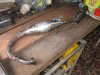
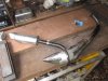
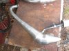
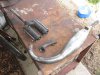
I gave my pipes a bit of a tidy up today, but something died in my Shipping container/ welding Shed.
And I have a few slag intrusions that should be fixed before painting, there's better light and less fumes outside though.
My 'Over the top' pipe needs a heat shield for the knee, it's burnt my mate also.
The header pipe for that one is salvaged from an old scooter and has a nice divergent angle. It was really a total experiment, with little math's and a bit of research, but again mostly about making something that fitted nicely.
I am however Quite happy with it's performance, although not really experienced enough to say that it is ideal.
For most engines/bikes/riders, a bit more header pipe?
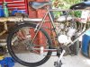
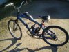
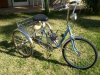
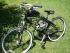
That bike/motor (The Old Raleigh) has had a recent pull down/ upgrage also,
But does not have adequate brakes for 50MPH!
So Is possibly going to get parted out, and the remains hung on the wall?
Otherwise It needs Twin Discs!
 

Attachments

  • IMG_3859_zpse3eecfa9.jpg
    IMG_3859_zpse3eecfa9.jpg
    121.1 KB · Views: 437
  • IMG_3858_zpsc1001802.jpg
    IMG_3858_zpsc1001802.jpg
    138.6 KB · Views: 296
Back
Top