Art Fish Mobile Motor Bike prior Motor Bike DIY'er build to add side car maybe?

GoldenMotor.com

MEASURE TWICE

Well-Known Member
Jul 13, 2010
2,742
1,212
113
CA
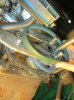
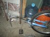
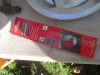
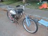
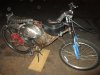
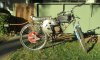
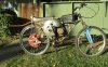
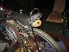
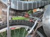
I got back to working on the motor bike, but before going to build the fish frame and cover right away I tried using the notched AX type v-belts. Oops, all lengths are too long.

The shortest belt I needed an AX18 and all they had was AX19. I may have to go online and order there where I might find one. The shipping and minimum order sucks though. I decided to just try using for that connection between top and bottom jack shafts, not to use pulleys and belts. I switch over to using a chain and two gears. They are the same size and so I am not getting the full approximate ratio 38:1 reduction for power up hill at slow speeds. I think I'll end up with about half being a ratio of 18:1 which will go a bit faster and not have the slow speed of 4mph with clutch just engaged with minimum throttle.

The other two longer belts are too long also, but I may be able to return them, only I may not have the receipt and it has been 3 months. I will see if they will do the exchange. One belt just is slightly too long and the other I guess if I measured or had the belt in hand to match up it would have been OK, but a 3 looked like an 8 on the 38 size I though I needed, it should have been a 33 inch.

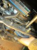
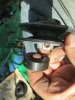
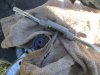
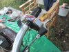
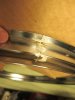
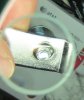
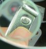
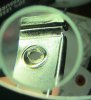
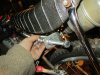
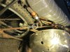
Using my chain breaker and installing the master link took a little finesse when I had to finish removing the link with my vise and a hammer and nail. The tool starts out OK, but will not totally remove the pin. Also the pin broke in half when trying to remove it, but it was to be thrown out later. I got some fine emery cloth to debur the link so it worked perfect with the master link to shorten the little bit of chain being used.

Monday Veterans Day I think it is, but the place that sold the belts mentioned they would be open Monday. I will call on Monday first to be sure, it could have been a Friday today that they were all frazzled and not thought about the holiday.

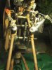
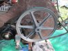
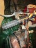
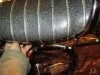
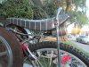
If I get the notched belts and install them, I still will be need to make a cover over the chain for safety as if it splits apart an whips up an away at me, well it is better it never reaches me inside a metal cover. The left side cover over the large 10 inch pulley is for the same reason. Safety is a must when 700rpm to 1000rpm and metal spinning on the jackshafts.

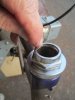
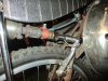
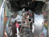
The chain with the gears, I can change a bit to get a gear reduction there, but I need to make a spacer for the smaller gear so it does not scrape on a part of the pillow bearing. I can probably get around 30:1 ratio using a shorter chain I'll buy and custom shorten to fit. There is also adjustment by moving up or down the lower jackshaft which will set the tension just right for the chain. The other two pulleys use, 1 and idler pulley and 2 an adjustable size pulley.

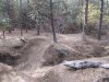
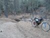
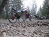
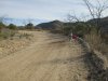
I can't wait to see what hills I can climb without any slippage of belts.

I'll also find some straight aways to try out some speed on trail riding.

MT
 

Attachments

MEASURE TWICE

Well-Known Member
Jul 13, 2010
2,742
1,212
113
CA
I have 1 of the AX notched type belts on and it grabs way better without being under as much tension. The other new AX belt was a bit too small and I'll be back at the store which I bought them from to return/exchange it as well as two other ones. I think the Gates TriPower AX belts are really what I needed. I will get an extra set to keep as spares.

The chain seems fine, but yet to try riding it again with the 2 ea new type AX belts and the chain replacing one of the belts.

MT
 

MEASURE TWICE

Well-Known Member
Jul 13, 2010
2,742
1,212
113
CA
The chain works fine replacing the short belt between the top and bottom jack shaft. The cogged belt to the back wheel works good too. I tried to get the right size belt for the centrifugal clutch to the top jack shaft's large pulley that uses a back idler to tension it up.

The belt I was using that is not cogged had the right length, but the cogged belt in inch increments was either too short or too long. I don't know if there is a 1/2 inch increment AX belt that I can find.

It does not really matter as the regular belt does not slip, it was really that the small 1.8 inch diameter pulley that has since been replaced with a gear and that is where it slipped the most.

I'll return the AX37's I got. I thought it could be adjusted to fit, but the back idler can only tension so much with the small area it can move. I could search for a smaller pulley and then get a belt that could tension with the back idler already made for the regular v-belt, but I'm not thinking it would be worth the effort. Today a test ride really confirmed that!

Overall there is a 14:1 ratio is what I have, but will see about other gears to get that to double to be 28:1 ratio that will be a real hill climber. Currently I have two 18 tooth gears in use that do no reduction as they are the same size.

I have a 13 tooth and a 18 tooth gear that I could use, but I would really need to use something like the 18 tooth and a 36 tooth gear if the cost is not way up there to get a 36 tooth gear, also will the 36 tooth gear fit in place.

MT
 
Last edited:

MEASURE TWICE

Well-Known Member
Jul 13, 2010
2,742
1,212
113
CA
I have a 28 inch gear and some new #35 chain on order and will be able to have 14:1, 21:1, and 30:1 ratio using permutations of 4 gears.

The gears I'll have: two the same number of teeth being 18 teeth, one with 13 teeth, and the largest with 28 teeth. I'll even see if I can fit all of the gears on at the same time just only using one chain that fits the pair in use at the time. A master link will allow to switch the gears used for a different ratio without having to disassemble one or both jackshafts to switch gears in use.

MT
 

MEASURE TWICE

Well-Known Member
Jul 13, 2010
2,742
1,212
113
CA
Some of the off road riding needs a little bit lower ratio than 14:1, so now I got my 28 tooth gear I am going to see about ratios around 20:1 and 30:1 and haul up hills.

I hit a rock the size of a brick with my front wheel I was trying to avoid, but there was gravel that made steering tricky and I hit it about center, but on about a 45 degree angle. The huge rock jettisoned to the right and the front of the bike hopped up. No damage was done an the wheel is still true!

MT
 

Attachments

curtisfox

Well-Known Member
Dec 29, 2008
6,046
3,949
113
minesota
Some of the off road riding needs a little bit lower ratio than 14:1, so now I got my 28 tooth gear I am going to see about ratios around 20:1 and 30:1 and haul up hills.

I hit a rock the size of a brick with my front wheel I was trying to avoid, but there was gravel that made steering tricky and I hit it about center, but on about a 45 degree angle. The huge rock jettisoned to the right and the front of the bike hopped up. No damage was done an the wheel is still true!

MT
The log in the picture looks like a aleigator liying there...........Curt
 

MEASURE TWICE

Well-Known Member
Jul 13, 2010
2,742
1,212
113
CA
I had some one else tell me that too.

The handle bars on my bike now are sort of ape hanger type, only they are just high up type, the end grips actually go out horizontally not down at an angle.

They are nice when seated on smooth ground so you have the hand grips at easy reach. They are just way too close and high up if you need to be standing on the foot pegs for much time.

Off road riding calls for standing on the pegs a lot as the banana seat is still nothing like a real motorcycle seat padded much much more. Even when I rode a Yamaha 125 I found for stability I would have to stand on the pegs anyway quite a bit of the time.

My elbows had to be in an awkward position when I was standing on the foot pegs and so I think I will be using these other handle bars from a bike someone was throwing out. It has the same size that fits my bike and there mountain bike type.

After looking further, I though if the fork could be swapped out and so I removed the bearing races and the cups and will see if the fork too can be used as it has good shocks and also the V-brake bosses already on it.

Then I noticed oops it is 24 inch and my bike frame is 26 inch. No matter I could just get a good knobby in 24 inch in the front and keep the rear drive wheel 26 inch as long as the fork fits.

I'll only be on a slant downward in front of 1 inch. (ie 26-24=2 2/2=1 ) 1 inch greater radius toward the top of the tire and 1 inch toward the bottom of the tire. You would only count the 1 inch less toward the bottom of the tire to consider how much lower the front of the bike would be.

This if it works would be really nice for the shocks being helpful when bouncing around trail riding. Going up steep hills I would less likely fall over backward. But popping a wheelie with the low gear ratio would be a little more trouble.

Anyone use a different size wheel in front or back than what was originally meant for the fame? Just wondered how it might handle different or be really not a good idea.

I have seen bikes made that the frame uses two different size wheels from front and back, but the frame makes up the difference. This would not be the case in my situation, there would be a slight tilt, but I think it would be minor.

I'll have another bike with shocks that is 26 inch wheel type, but it is a different size diameter for the headset and a different kind way the fork attaches to the handle bar stem, so I cannot use it.

MT
 

Attachments

Last edited:

MEASURE TWICE

Well-Known Member
Jul 13, 2010
2,742
1,212
113
CA
I wanted to go to get parts to get my motor bike back together. I was just changing the gears part of a belt and chain system to get low ratio for off road up hill trail climbing, when I noticed something else needed attention.

I have a large driven pulley that started to slip sideways off the end of a jack shaft. I intend on either threading the end of the jack shaft or using a slightly longer jackshaft where I will put on each side of the pulley a split collar to really keep it in position regardless if the forces are too much for the set screw holding the key.

This large pulley does not have a second set screw at 90 degrees to the keyway set screw and I can’t trust it to stay put. I was told I could drill and tap the pulley to make the second set screw usage, but these clamping split collars do not mar the jack shaft and have never failed.

I already tapped the crankshaft of the engine to keep the belt clutch on even though it has the keyway and two set screws. I felt better be safe than sorry. Anyway I heard some sound that made me thing something had gone wrong, but nit much extra noise. The bike kept going strong so until now I did not think too much of it. I can make a small inspection access door on the metal cover so I can peek in for inspection without unscrewing the whole cover.

I have metal covers over the clutch and the first large 10 inch driven pulley so I was safe from harm if it were to give way. It would have wrecked a bit I expect, but lucky it was about only 1/3 about to come off the end of the jackshaft. There is nothing but the key needs replacing besides my modification to be sure it does not do that again.

I also noticed that one of the keys that I have on the bottom jack shaft was not completely underneath the set screw used with it. The key that I need to use there must be not the curved end type that I got a kit of keys from Harbor Freight. I need to either grind the ends flat and straight across or get others somewhere else that are not curved at the ends.

The adjustable diameter pulley I have has the key way set screw so close to the edge of the side of the pulley. It would not be and issue if I did not put a split collar on each side of the pulley, but I find them necessary with so much at stake if the pulley were to move. All the other pulleys have the set screw location not so close to the edge it does not matter if I use the rounded edge type of keys.

I got the #7 drill bit and 10-32 tap ready to mod the jackshaft, or I might get another jack shaft kit and keep the extra parts on hand for when something wears out or breaks. It then will have to wait an extra day, but I am getting rest from my last time off road riding. I’ll work on the temporary change over to the mountain bike handle bars and maybe a fork with shocks.

MT
 

Attachments

Last edited:

MEASURE TWICE

Well-Known Member
Jul 13, 2010
2,742
1,212
113
CA
I got the tools out and tapped one end of the top jack shaft with a 1/4-20 thread.

Now I have the large diameter pulley soon to be sandwiched between the fender washer held in place with the 1/4-20 bolt with split lock washer and on the other side to use one of the split collars.

As the jack shaft turns the bolt will self tighten due to the rotation, just as the one on the clutch at the end of the engine's crankshaft.

I forgot to get at the hardware store the squared off end keys that I need for the pulley that has the set screw so close to the edge. I will just hacksaw or grind it square if I am not near there again.

MT
 

Attachments

MEASURE TWICE

Well-Known Member
Jul 13, 2010
2,742
1,212
113
CA
I have an alternate handle bar that is narrower and lower for off road riding. The fork that I have to use with it has shocks and also the same kind of strong braking system. The v-brakes type but already built into the 24 inch fork so don't have to weld anything.

I have a new tube and tire for the front which is 24 inch I put on next time I get a chance. Even though I loose 1 inch height from using front 14 inch rear 26 inch the bike is still level.

It is that the shocks on the front even keep the front so high. Only if I were going over a good bump then it would be lower. The center stand down does not lift either front or rear wheel off the ground when the bike is at rest.

It is OK though. I guess I could make the feet taller or put some shim where I have the bolt under side. If I had stuff to do aluminum welding better I might just make the feet taller by welding on to them. The rubber feet I globbed some extra rubber RTV to make them not fall off. There wearing off now. A nice size flat of metal attached to the feet would work better in leaves and would be nice.

I'll think of something, but it is OK having a four point stand (ie two tires and the center stands 2 feet).

The test of the 22:1 ratio can so far as tested go up much more considerable climb without any run up. It has real good acceleration and the short piece of chain between the two sprocket going from top to bottom jackshafts run real smooth.

I have to get shorter rear brake cable and throttle cable, but then its time to hit the dirt trails and hills again and get a real good idea how it goes!

MT
 

Attachments

MEASURE TWICE

Well-Known Member
Jul 13, 2010
2,742
1,212
113
CA
I had to trim off the bottom of the head tube when the fork with the shocks I switched to did not have quite enough threads for the end play nut, washer, & crown locking nut. I took off 9 mils and now the top crown lock nut has a full five turns to torque down. There are only 2 more turns of thread under the crown. I know you don't want to use them all as to bottom out the thread would have the lock washer not get the pressure it needs to lock.

Need another time to put on the new shorter cable and cover for brakes and throttle, but I'll do that right as soon as I can.

MT

PS I was going to trim both top and bottom of the head tube to get enough thread protruding. Both the top an bottom of the head tube inside had limits to how much could be cut off without cutting where it connects to the other tubes that are all brazed together. I thought I would need to do both bottom and top, so you see the blue dye on the top, but I did not cut it as it was not necessary.
 

Attachments

Last edited:

MEASURE TWICE

Well-Known Member
Jul 13, 2010
2,742
1,212
113
CA
I shimmed the handlebar to fit the kill switch which otherwise had too large a diameter to clamp on well. I use a cut up Schlitz beer can and electrical tape. The external star tooth washer against the soldered ring terminal with the fastener makes a second wire for ground. I run dual wires.

The shorter cables for everything when going from easy rider handle bars to off road trail riding handle bars all done.

MT
 

Attachments

MEASURE TWICE

Well-Known Member
Jul 13, 2010
2,742
1,212
113
CA
The pull cord start is now accessible while seated on the bike through the right side cover. I tried the extension of the exhaust for when the fish cover is on for parade events. The exhaust must exit further back so to avoid carbon monoxide asphyxiation. Fire proof spray on the fabric cover tested and only will char and not keep burning.

Still at the location of the exhaust I think some fiberglass cloth with matching color of the fish fabric that goes over the skeleton frame will be in order.

I rode with the double length of corrugated copper exhaust with the copper gaskets replacing the rubber ones and no noticeable loss of power at all.

I found 22:1 ratio probably fine for off road riding (2200 rpm to 3500 rpm with 8.1 mph to 12.9 mph), but will try the 8 tooth gear with the 18 tooth gear and chain custom cut to size for 31.5:1. That ratio includes the two belts and pulleys (14:1). (18/8) * (14:1) = 2.25 * 14 = 31.5

The speed would then be 5.4 to 8.6 mph with 2200 rpm to 3500 rpm with a 31.5:1 overall ratio.

Still on second thought I might use the 28 tooth and 8 tooth gear. 28/8=3.5

3.5 * 14 = 49

49:1 ratio at 2200 slowest speed clutch fully engaged 3.5 mph.

49:1 ratio at 3500 fastest speed 5.5 mph.

The centrifugal clutch pulley and the other 3 pulleys are not ones I would change, they have been used with two gears of the same size for 14:1 ratio, but it won't do big hills. A torque converter that may be something I could think of adding and remove the regular centrifugal clutch. The 30 series Comet asymmetrical torque converter could make 0.9:1 overdrive to 2.68:1.

If I multiply that range by the 3.8:1 of rear drive pulley arrangement and the 2.25:1 gears ratio I have 8.5 that will multiply by 0.9 range to 2.68. That is
7.65:1 ratio for fastest speeds and 22.78 good torque for hill climbing and not too low a speed, still about 10 mph.

I'd have to shim the crankshaft for 3/4 inch for the drive clutch, but 5/8 inch is available in the 30 series for the driven.

Maybe I'll see. I'd have to make the left side cover a bit larger for the drive clutch being about half inch larger diameter.

MT

PS: Did the math for the torque converter it would be 7.5mph slowest full throttle on the flats using the 18 and 8 tooth gears. Fastest would be 35.2 mph.

That 7.65:1 was close to the 8:1 I had before I set up dual jack shafts to have extra pulleys (eventually changed to gears and chain) for lower ratio when I have the large 26 inch wheel and want torque to climb.

I remember the clutch did not like starting out from a dead stop, 8:1 was way too much for a start. 22.78:1 is just like now using a regular centrifugal clutch with out a ratio that ranges, but is stuck with 21:1 ratio. The torque converter would allow starts at 22.78:1 but eventually be at 7.65:1 for some flat speed record runs.

I can just imaging at 49:1 ratio, the slower speed (3.5mph) with enormous torque using the 28 tooth gear and a 8 tooth gear connecting top to bottom jack shafts. Tractor type pulling events here I go!
 

Attachments

Last edited:

MEASURE TWICE

Well-Known Member
Jul 13, 2010
2,742
1,212
113
CA
Trail riding in OHV mode. Nice weather and the bike climbed most what I felt like doing. Just gravel in the bottle of very deep ravines that just a few trails would cross, I had to walk it powered through. The wheels are not like a motorcycle so you have to use good judgment so you don't over do it.

MT
 

Attachments

MEASURE TWICE

Well-Known Member
Jul 13, 2010
2,742
1,212
113
CA
The Whizzer type sheave from Whizzer Paul in USA (from China), I got the clamp threads to need a little cleaning with a tap and cutting fluid on one end.

Or maybe I should use the Dremel grind disc and just take off the ruff edge as you can see in the magnified photo jpegs attached?

Other than that, just the weld grinding could have been a little better on the sheave. I'll use 400 emery cloth and it will be fine

I expect it will be just fine and am waiting for my 12 gauge spoke heavy duty wheel to arrive from Amazon.

MT

PS Otherwise I find the rest of the press plated metal sheave looking quite nice!
 

Attachments

Last edited:

MEASURE TWICE

Well-Known Member
Jul 13, 2010
2,742
1,212
113
CA
Additional info: PS: I think the threads on the sheave clamps are akin to Stover Nuts. All Metal Locking Nut that deform a portion of the threads intentionally.

No instructions mention this as it came without any instruction either printed or on Ebay, but this is probably the case. The seller did not mention this as was probably unaware of what he was looking at of the pictures I took that I sent him.

Without my request I have been sent additional hardware and expect it to be the same.

http://www.garagejournal.com/forum/archive/index.php/t-85569.html about All Metal Lock Nuts

http://en.wikipedia.org/wiki/Distorted_thread_locknut about Distorted Thread Locking Nuts

The problem with this kind of locking mechanism is after a few uses the parts cannot be separated if galling occurs.

Centering the sheave I would end up if necessary using a Dremel to slice the head off the screw an do my best to avoid hitting the sheave to get it all apart to adjust the sheave.

The remaining stuck threads in the clamp part I could then Dremel cut off wheel the threads flush and drill out the center and have no threads left. Then just use a slightly larger screw with nylon locking nut.

With nylon locking nuts, yes they wear out after a few disassemblys and reassemblys, but I also add split lock washers to the deal to insure it stays.

Replacing a few nylon lock nuts at the cost and time saving is a better idea I think.

I would be inclined to drill out or just grind away the deforming portion of the clamp threads and add both a nylon locking and split lock washer before I start installing anything at the start.

I even could just use the split locks for the time spent centering. Once it is tested and perfect, I would go back and add the nylon locking nuts.

Removing one fastener at a time nothing is going to move as there are 18 fasteners.

MT
 
Last edited:

MEASURE TWICE

Well-Known Member
Jul 13, 2010
2,742
1,212
113
CA
While deciding to do as I mentioned above about removing the deformed threads on the sheave clamps, I first went to get the nylon insert lock nuts and cap socket head screws. When at the supplier I found that one of the screws actually went through the threads without using a screw driver. There was just very slight amount distortion on the threads.

It seems and confirmed by the sales person that these clamps do not have the equivalent of metal locking nuts. I will eventually go ahead and remove the deformed portion of the threads, but that will leave still to use the new 5M screw, lock washer, flat washer, and nylon locking nut.

I bought a 5M tap to clear the threads and may see if after grinding off the deformity that probably was just a non-intended part of the formation of the clamps, that I could omit using the nylon lock nuts. I'd think that seeing how the threads are the way they are now, that I probably will not trust them alone without using the nylon lock nuts.

MT
 

MEASURE TWICE

Well-Known Member
Jul 13, 2010
2,742
1,212
113
CA
Some Central California OHV trail riding, not me at this location riding as my bike is being repaired. I took the picture while checking out the location.

Exhaust tube redone where clamp I used before was on the corrugated section and cracked. I used some copper to spread the stress out, but on the end edge it cut through after about 2 years of use.

My current idea is still much the same but I used a heavy hanger copper part for water pipe, and it clamps on to the cast iron portion, not the corrugated stainless steel pipe.

I use on its side with the same threaded rod to angle bracket to seat post.

I am using now stainless steel corrugated easy to make the shape, much like the copper corrugated I used before.

I reused the copper gaskets (I made special see past posts) and swapped out the rubber parts for them. The galvanic protection nylon parts at the ends of the tube also removed.

I have to drill a hole in the bracket holding the muffler pipe and make it more under the middle of the seat as the different clamp I got is off set more. I can also cut the extra threads off some too. Then my leg or thigh will not be near the mounting hardware.

A drain screen made of aluminum mesh I may add to the muffler to protect against accidentally touching it under the seat. Also aft of the seat the muffler is about an inch further back. A cover of the same would be fine.

I see that I might just weld a short piece of threaded pipe to the screw on flange mount to the muffler to shorten in an inch back under the seat like it was and worked out fine before. The cast iron coupler then could be removed all together, just still using the lock nut to position the muffler correctly.

No heat problem for the rider or the wheel, but it still is dangerous if touched.

The rear brake cable is intentionally disconnected from one side just for the moment. The cable does lightly touch the top of the exhaust pipe, but as much heat actually travels through it never melted the shoe pads. I don't think I really need to raise both side for the pulling mechanism. I think I could add a metal roller support if necessary.

The left side cover over the 1st of three ratio reductions for torque is removed temporarily so I could access the exhaust port of the Briggs engine and swap of the cracked exhaust pipe that lasted only 2 years for a bad mounting clamp design.

Absolutely no way do I run the engine without this cover on. It is just about a 1:3 ratio at this point and with the range of clutch engagement from 2000 to 2200 rpm and then up to maybe 3500 rpm, you have essentially a saw table on edge!

The spark arrestor type muffler also has the optional deflection part that the 4 self tapping screw go to on the back, but they would not be a good idea for my use. Just straight back works good.

In a week I should have the longer axle I can install in the new wheel that I got with 12 gauge spoke.

Since I found that the replica Whizzer sheave I bought will work with the thinner spokes on the wheel I already was using with my home made pulley mount, I will maybe for just a short while mount the sheave on that to get it all going again.

I sort of like the more wooded areas to ride, but I can imaging maybe with enough suntan lotion on and the protective gear I could try to see if my bike could get enough speed and torque to do the lower hills as those see in the foreground image.

The two seen riding, they have those two and four stroke little motorcycles with at least 3 or 4 gears. They do the hills as seen in the distance as well, but my bike would not do that much of an incline.

MT
 

Attachments

Last edited:

MEASURE TWICE

Well-Known Member
Jul 13, 2010
2,742
1,212
113
CA
I set up and tested the new clamp on the tail pipe and it worked great!

The picture on its side I'm not sure if it would post in the vertical view unless reduced pixel. Anyway see the nice bluing starting on the stainless steel corrugated pipe.

MT

PS, I guess it will look nice with contrast when the frame is painted red. Then just paint some white some where too. Patriot colors!
 

Attachments

Last edited: