Art Fish Mobile Motor Bike prior Motor Bike DIY'er build to add side car maybe?

GoldenMotor.com

MEASURE TWICE

Well-Known Member
Jul 13, 2010
2,744
1,219
113
CA
Somethings fishy here? Just a start to mod the bike to become a mutant motor bike fish mobile. I have to get the hula hoop bent to a tighter radius or use something else. Length should be not nearly the same as width. Or top of fishes back to bottom of belly should I say.

MT
 

Attachments

MEASURE TWICE

Well-Known Member
Jul 13, 2010
2,744
1,219
113
CA
I had tried my new regulator that was a courtesy of Hobart when my 1.5 year old with a 1 year warranty MIG regulator started acting up. It still may work OK with a tank that is under 1000 psi, but won't know for sure till either my tank is down at the pressure or I borrow a friends tank that is. The new regulator worked fine. All I had to do was swap the hose from the old one so I could hook it up to the back of the MIG.

My training wheel braces I got an idea using channel slotted steel metal and welding it to the frame parts on the bottom just forward of the rear drop outs. This will keep it from being just only held on with the bolt that I have going to the threads I added to the drop out. I am keeping the attachment point separate from the wheel axle. 3/8 inch thread is quite thick for the training wheels, but from more than one point. The extra brace I will also bolt to.

It might be hard to imagine, but later you’ll see. I think when I use with out the training wheels for off roading, I will not be bothered by this metal brace that is welded to the frame being in the way. This is since it will be close enough to the frame. Things sticking out could hit the ground and have you take a spill I know and took that into account.

I felt I should practice on some metal that was similar the bike frame where I will be welding. I used the handle bars from a kiddy bike that was being tossed out by the dumpsters. I ground off the paint where I was to weld. I clamped the channel metal to the round hollow tube on the handle bar. I really could have used the larger diameter bar not the cross piece as I did but OK anyway I got an idea how it welded.

I had all this extra channel metal that I need for the two side braces still left welded on the handle bars. I tested how strong it was and that was with just half the channel metal welded on. With the bigger diameter I'll have both sides easy to fillet weld together.

I later also used the angle grander with flap sander. Sorry the picture of the weld before sanding focused on the bench and not the work. I cut the extra metal off after being satisfied I can weld to the frame OK. There is enough channel metal I will start on it weather permitting ASAP.

I'll also do some welding to make better for the foot pegs what is necessary. I will also leave it so I will be able to remove the foot pegs with the bolts that they have.

The prior work I did before I had the welder left the cut of metal way to little supported and with to little metal and I bent the part that I bolted the foot pegs to.

I was standing on the pegs while bumping over rough ground during a test run as a dirt bike with out the training wheels for art cover and they are sagging now. My rear got a bit too much and now I know the banana seat is only so good. Standing on the pegs will be necessary for some more off roading bumps!

MT
 

Attachments

MEASURE TWICE

Well-Known Member
Jul 13, 2010
2,744
1,219
113
CA
I put off the welding of the art cover training wheels braces and got the belts working really really good.

I sanded just a few of the pulleys. The ones that had paint, I only cleaned. I think smooth is what I want not roughed up so I used fine maybe 320 grit. But cleaned definitely so that is done and no oil residue from possibly the engine before gasket changed on the oil breather near by.

I sprayed on a belt I was not using for test first with a pulley using the CRC Belt Conditioner stuff. It does help. It sort of makes a mess on stuff if you do not take the belt off the pulleys. Dirt and grime is attracted to the over spray, but I'll clean that later. The pulleys really grab the belt or visa versa!

I think it also might make the belts stretch a little after applying, but the belts as there new stretch a bit anyway and I have some adjustment I made for all three belts.

Finally tried it out and nearly or did a little lifting the front wheel off the ground.

Then later I had the belt slipping bad and heard some rubbing.

There was one belt I thought was way loose and it stretched. I found out it really did not stretch at all.

After looking closely I found on one of my two twin stacked jack shafts, a pulley had moved sideways and the whole bottom jackshaft allowed the left side pillow bearing to come out of the holder.

The belt loosened due to that, I had some metal scraping on the jackshaft and made two very fine grooves. There no where that they are problem when I put the pulley back where it should be. There from the inside cover that the jackshaft rested on when it moved sideway and the pillow bearing came out the holder. It is on the end of the jackshaft and really no problem at all.

Lucky that it is not a big big problem, but have measures to keep this from happening again!

I intend to add a bushing beside the pulley to keep it in place. The set screw and keyway also will be used, but this split collar will be an extra safeguard. I had the belt rubbing on the side of the knobby tire as a result of this, but it is OK.

Maybe I will use some Loc-tite Blue on the threads of the set screw for these.

Anyway I was surprised that the hill climbing was stupendous! 40:1 ratio with a 3hp Briggs 4 stroke going with the centrifugal clutch was nice to try out with no slipping belts.

Mind you, that I will eventually try it with a 20:1 ratio for more speed. It really is this way for under 5mph parade speeds with the fish art cover and training wheels, just above idle to engage the centrifugal clutch.

MT
 
Last edited:

MEASURE TWICE

Well-Known Member
Jul 13, 2010
2,744
1,219
113
CA
I've not looked at the jackshaft pillow bearing and holder again, but had a thought.

The bushing split collar did not loosen on the jackshaft that had the pillow bearing come out of the holder. The other side pulley without any bushing split collar I just remembered that it did not have the set screw come loose. It just had so much force side ways.

This sideways force was probably due to when the pillow bearing that came out of the holder and the shaft was at an angle only in the other side pillow bearing. The belt still stayed on the pulley but slackened. The belt slackened even rubbed on the tire.

A bushing split collar will be used in the future, besides just the set screw on the pulley pushing on the key in the keyway on the jackshaft to hold the jackshaft in place. There is enough room to use both.

The bushings have much better side ways slipping prevention that the pulley alone has due to more surface area. A key in a keyway does not do any where as well.

Bushings will always be used even if a pulley is close enough to the pillow bearing. It could be shimmed to fit in between or on the opposite side up against the pulley.

There is that the pillow bearings I am using has a metal ring around the perimeter to keep it from sliding completely through the pillow bearing holder. Since the bushing or bushing and pulley are inside the brackets and pillow bearing holder on the jackshaft, I thought it might be better to have the bushing on the outside instead.

That would have that outer ring on the pillow bearing such that it cannot slide inward unless it breaks. I know I would have to also put a bushing on the outside of the other end of the jackshaft to do this or the jackshaft is not set in place. I have enough room I could do this as well.

The cover I put on the same bracket might have to be modified to do this, but it would have better capability of preventing the side ways force that comes from the drive belt pulling backward on the left side of the jackshaft. The belt connecting the bottom right side of the jackshaft that is pulling upward toward the top jackshaft also probably contributes to the side ways force.

There is one other way I think I could do this. If I just make a retaining ring that pushes up against the pillow bearing to hold it in place instead of a split collar bushing that takes up more space.

Better pillow bearings that already incorporate the holder and are not having a fit that are somewhat loose to allow assembly could be a better option.

Short of that, I know that the pillow bearing holder that came with the jackshaft kit does not provide for using all of the width of the pillow bearing in the holder. The holder is not deep enough.

I think I may add an extra holder to make a double thickness on this left bottom side jackshaft as that is where the most forces is trying to pull the pillow bearing out of its holder.

I know from the past motor bikes built that the stress on the belt was only a direct drive from the engine crankshaft to the rear drive pulley. It had no side ways force present.

The need for this multiple pulley ratio reduction has the bottom jackshaft with this problem that can be fixed with out the need for additional expense of better pillow bearings, but I shall go window shopping anyway.

The pillow bearings marketed that are floating and also have grease filling connections if are easy enough to incorporate into what I already have existing could have me buy them.

MT
 
Last edited:

MEASURE TWICE

Well-Known Member
Jul 13, 2010
2,744
1,219
113
CA
Again, I have not yet looked at the bike yet, but have really thought about what happened. I think when a pulley was moved sideways on the bottom jackshaft when the set screw had not loosened I think this is what happened.

I do think though the pillow bearings and the holders are sufficient, but alignment of the pulleys needs to be a bit better.

The rear wheel drive pulley possibly just slight enough at an angle to a pulley on the bottom jackshaft left probably forced the pulley and jackshaft as one unit to the right. The bottom jackshaft pulley right did not hold the sideways force and the jackshaft slipped through it enough to cause the opposite side pillow bearing left to come out of the holder.

I did not have a bushing keeping the right bottom pillow bearing right in place, just the bottom jackshaft right pulley.

The keyway and set screw in a pulley is good to keep the key in place but not this sideways force.

The sideways force I shall do best to eliminate all together by lining them up better. A chain would not work with that misalignment and jump the sprocket, but my belt just kept on going even when this all happened.

If I make a zig zag shape to the left side rear drop out, then I would have more room, but I have only just spread the left side slightly with shims. I have to be sure the belt does not hit the tire or the frame tube going to the left side of the drop out.

Putting two more of these bushings in place, and I could probably leave the angle as it is, but I'll try to straighten it out. What I'll add is one bushing up against the left side of the right pulley and another up against the right side of the left pulley. The bushing already on the left side pillow bearing pushing it as far as the snap ring will allow is already existing and stays too.

MT

PS:

Now that I know I can weld the frame with my MIG just fine, I just need to be able to jig it up so that the frame is true if I go to modify the left side drop out tube to a zig zag shape.

Thinking it just won't be necessary if I just try to optimize to belt not to rub, but be as straight as possible.
 
Last edited:

MEASURE TWICE

Well-Known Member
Jul 13, 2010
2,744
1,219
113
CA
I cleaned off the over spray from the belt conditioner. I used Goo Gone. Then followed it up with a clean rag of acetone to get any of the oily substance from the Goo Gone off.

The crank shaft I tapped a 1/4 - 20 thread for a bolt and lock washer and flat washer. Also underneath all that a flat washer that I Dremeled the inside to get clearance for the end of the shaft. Now the play that the bushing in the centrifugal clutch has is all the play it has. I still have the set screw in the clutch and may also treat with the Loctite Primer and use Blue Removable Loctite.

I have metal parts all figured on how the braces for the training wheels will be attached for when I'll be going very slow and having the art frame for the fish cover on.

I would have liked to test out the hill climbing again since I cleaned off the belt conditioner over spray and added two more bushing to make it more sturdy, but that will have to wait. The welding would mean just removing it again and its not worth it. I'm quite happy with the power and now it is fishing time.

MT
 

MEASURE TWICE

Well-Known Member
Jul 13, 2010
2,744
1,219
113
CA
The training wheels are coming together nicely. I made sturdy mounts so that they hold the weight. The 10 inch inflatable tires with triangle bracing fixed them up much better.

I did however in the process found that earlier threaded bosses I made for possible mount of the skeleton fish frame broke the weld on one side. The frame not broken, just the small area welded boss to the frame.

The small surface area of one 3/8" thread welded boss used to hold the force of the whole motor bike falling over sideways as compared to the multiple threaded bosses for a light weight art cover slipped by me.

I guess I would have used the axle to mount it but all the threads had been used and it would be difficult to find or make a longer axle.

This has me also making some gussets to the rear drop out now as I see the force as a twisting motion and would like it not just applied to the crux where the flat drop out slots are.

I have extended the training wheel mounts so that they are further from the rear wheel and give greater stability. I also can imagine now it much more easy to swing my left leg over the banana seat and then have both feet just clearing the right side training wheel. A door to the skeleton fish frame would be prior swung open to allow egress.

I did find something very interesting when MIG welding areas of the braces where metal parts joined had come together at 90 degree angles over a few inches. The weld puddled was very smooth and I figure the shield gas gets cornered in a works better. Would creating a whole atmosphere of shield gas and using a SCBA rig to breathe be the way to insure shield gas present fully, just a dream?

MT

PS there was once I was in a building they said you could not stay inside too long without SCBA as the atmosphere within it was for the apples harvested stored for a short while. They added a higher concentration of nitrogen to keep the apples fresh. The apple cider was the best!
 
Last edited:

MEASURE TWICE

Well-Known Member
Jul 13, 2010
2,744
1,219
113
CA
Offroading with the dirt bike version, worked well. I got the all three belts tensioned and then tried it. It would hop at start if full throttle about an inch or two the front wheel off the ground.

Later I found the belt around the very smallest, 2 inch pulley between twin stacked jackshafts had the top edge shaved off. Small green particle of the belt were dusting the metal brackets below. I loosened the belt a little and it still had good grab power.

While I was later using it offroading it still had some of this dust from the belt but ever so fine a grit. More like a powder it was. I think I could just leave it now as it has worn in place and has stopped. No more debris from the belt.

I got an idea how long I can ride and then need to gas up again. It is not as simple as looking at would be even with the bottom seen from the inside of the tank. I had still a bit more gas than that. The outlet for the gas inside the tank I know has a tube up a little higher to restrict getting sediment if present. That means the gas must be above that.

At one point the engine died and I got it started and no problem running, but I would guess with the gas tank low, it sucked in some air in the line when on a bumpy incline and it needed to be purged out. That is not worth the effort to mess with, gas up before that happens. Walking back for that reason alone is not so smart.

With previewing the trail with a friends Yamaha 125 I was thinking it may be too much for my Briggs motor bike going back up the trail as the incline was a bit. The bumps were not to bad and the loose gravel on the trail you had room to go around usually.

I was cautious to where I turned around so that I had a running start. It did it fine. By the way there were some trails that I would get so far and just turn around. This even on the Yamaha 125 I would not have attempted. I'm not that good a rider. I saw a gully about 10 feet down and 25 feet across and knew the machine could handle it, but even if you fell and were OK, how to get enough running start when the flat on the bottom of the gully was only 3 feet across!

I guess in that case you use the engine to get it out while you walk besides the bike, your boots hopefully grabbing as well as the bikes knobby tires.

I know I did that with a 350 street bike when getting in an enormous pot hole on a less than well maintained city street. Then I had to stop for a red light and when I stopped my feet could not touch the ground. I had evaded falling over all the way, but there was no way to hop back on while in a rut.

One other part of a trail I turned around when I saw a groove about foot deep and a foot across, flanked by normal ground level just a foot and a half on each side. It was not a straight run either, it curved a bit. Trying to stay out of it was not the approach as I heard from another rider. He said he just when through it. My clearance on my bike is not enough and my pegs would probably have folded up as they are that type, but I would still get stuck.

Later I will change the memory size of some pics on my camera so that I can post. I need to load software on this computer I'm using which the other computer had that made it possible, but is now inoperable.

MT
 
Last edited:

MEASURE TWICE

Well-Known Member
Jul 13, 2010
2,744
1,219
113
CA
Just in case you asked to see:

The offroading pics!

Unfortunately no pics from the trail riding. Another time.

MT

No I didn't hop that 30 year old fell tree, but I ducked to avoid my face whipped by low branches on the trail. There was some loose gravel and rounded bumps I stood on the pegs to keep from a painful rear.
 

Attachments

MEASURE TWICE

Well-Known Member
Jul 13, 2010
2,744
1,219
113
CA
I got back to finishing a few more of necessary stuff for the art fish mobile.

The large 10 inch inflatable tire training wheels need study brackets. I got to welding the 2nd of the two.

There needs to be some more gussets and bracing of the frame near the rear drop outs to make these mount and evenly transfer stress.

The bike with art cover should not tip over as the training wheels are far enough apart. Additionally the brackets are of thinner hollow square and round tubing and also flat 1/4 inch steel bracket angle metal to not break under stresses.

More photos in next post of the work.

MT
 

Attachments

MEASURE TWICE

Well-Known Member
Jul 13, 2010
2,744
1,219
113
CA
Some pictures of the beefed up mounting points near the rear drop out for the separate bolt on place for the training wheel brackets on the right side so far. I will later drill the hole for the training wheels axle on one side to go through the bottom part of the bracket. Just not enough time today to get that done.

I did however test the bracket in a way by shimming with a piece of wood and metal to tilt and rock the bike over to the right with the center kick stand in the up position. I did not see the frame flex much. Later with the training wheels on it and I'm sitting on the bike seat I'll lean over to the side and see how it holds up while not underway. Moving and leaning I will try when going slowly, but probability with out the engine running and just having it coast or some one push it.

Then the live check out. I want to be able not to have to worry about needing a kick stand at all. When the bike it all set with the fish outfit I'll need not to think about dealing with falling over moving so slowly on uneven ground.

I took off the gas tank for safety while welding. The wheel with the drive pulley I removed also as putting it on and off is more troublesome that the temporary wheel I am using while making these training wheel brackets and mounting points near the rear drop outs.

The additional metal from the mounting point near the rear dropouts I may leave as is to see if it can be used to help hold the cigar shape fish body frame and the door to access through it to egress the banana seat. I have to see about how much weight the tail frame portions of the fish art frame will be, as just adding it to mount to the back of the banana seat sissy bar may not be enough.

Also temporarily I have the right side engine cover off as I needed to be able to get at the fuel line hose inlet to the carburetor to remove the gas tank when doing the welding.

I don't think another wheel or tail skid like on a small airplane will be in order, but who knows.

MT
 

Attachments

Last edited:

MEASURE TWICE

Well-Known Member
Jul 13, 2010
2,744
1,219
113
CA
I'm going to see when I get a chance to swap in this cogged AX19 belt on my short belt that goes around about a 2 inch diameter pulley on one of the two jack shafts.

I'm hoping that it will grab better and if not, it was only $14 at Graingers. The short length cogged AX18 was what I wanted but the shortest I could find without shipping cost and $35 minimum order elsewhere meant I can make an adjustment to use the AX19.

In 2011 the European PDF file I found specified GoodYear Torque Flex (V-belts) ISO to go to AX16 at the shortest length, but I could not find AX18 GoodYear part anywhere in the USA.

If I decide to still want to try for using a chain at some point I have two gears that I will use to keep the same ratio of divide by 2 approximately. That would be the using 2 belts and 1 chain, achieving the same ratio around 40:1 reduction.

If it grabs better however it is accomplished, I will be giving the hill climbing a little more assertion!

The other two belts also have on the smaller of the two pulleys about 3 inch diameters, so I found a supplier Kaman that has the Gates Tri-Power AX38 and AX58 cogged V-belts each for about $8 each (better price than Auto Parts Stores), so I might get those also and see if they perform better.

I won't be thinking of using a chain and gears for the other two belts as the larger gears to fit on a 5/8 inch jackshaft and also use on the spokes of my rear drive wheel just cost too much to go that route.

MT

Daton AX19
http://www.grainger.com/Grainger/ww...ch&Ntt=3vu38&N=0&GlobalSearch=true&sst=subset

Gates AX38
https://ec.kamandirect.com/us/catalog/part.jsp?PARTID=5506284

http://www.gatespowerpro.com/Comerg...oductDetail&removeNav=true&productID=90122038

Gate AX58
https://ec.kamandirect.com/us/catalog/part.jsp?PARTID=5506444

http://www.gatespowerpro.com/Comerg...oductDetail&removeNav=true&productID=90122058
 
Last edited:

MEASURE TWICE

Well-Known Member
Jul 13, 2010
2,744
1,219
113
CA
Thanks CF, I checked Dayco AX V-Belts for smallest size length and it was AX21. I called them on the phone as well and had that confirmed just now.

Quite a few online non-name brand belts are being sold that are as small as AX16, but they are online mail order with that minimum purchase catch.

I would pay shipping, but I don't need 9 extra spare belts.

I have a few pics of the belt below that I got.

Those places that sell Dayco I know are not near by, except maybe 90 miles round trip to Tractor Supply in Gilroy, CA and Farm Supply they are a couple hundred miles round trip.

I'm happy with an outlet that sells no minimum and no account needed and I am often enough near by that it makes no difference that its 40 miles round trip since I'm otherwise just an extra 2 miles to stop by there.

Have you used the cogged AX belts used with 2 or 3 inch diameter small pulleys and found them to work better than the regular non-cogged since they flex better around the small pulleys?

I'm hope for a significant increase in grab.

MT
 

Attachments

curtisfox

Well-Known Member
Dec 29, 2008
6,048
3,955
113
minesota
Doesn't some of the auto parts stores sell Dayco? Call one of the supplyers and see if they would ship one...........Curt
 

MEASURE TWICE

Well-Known Member
Jul 13, 2010
2,744
1,219
113
CA
Hey thanks, PepBoys and AutoZone nearby have Dayco parts.

Only thing still is that I have to know the Dayco Part first which I'll check there site and maybe visit one of the stores. On the phone and web sites the store people are quite useless unless you have year make and model number. Ha! My reg for CA OHV says SPC special I suppose?

Inside Length 38 inch / Outside 38.27 inch and 0.53 inch Width
http://www.accessdayco.com/AdditionalInfo.aspx?Part=17380

Inside Length 58 inch / Outside 58.27 inch and 0.53 inch Width
http://www.accessdayco.com/AdditionalInfo.aspx?Part=17580

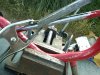
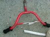
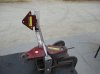
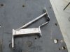
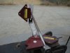
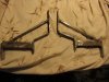
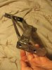
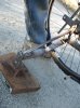
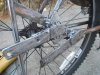
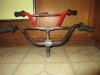
I see the notches cogged or whatever on the back of the belt. I could use this for the 58 inch for rear wheel drive to bottom jackshaft pulley, but not engine clutch pulley to top left jackshaft pulley as it has a backside idler in use. I am pretty sure it would do something to the tracking on center of the idler?

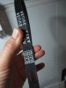
I can call tomorrow Dayco and see if they have the coggs on the inside like AX belts I've seen.

In any case the 0.53 inch width Dayco v-belt has a shortest length of 20.8 inch inside and effective / 21.37 inches outside.

The prices are higher than the Gates Belt from Kayman when I checked Amazon it was $17.68 an add shipping. Also Amazon has a picture showing coggs on the outside which conflicts with the picture on Dayco Company webpage. Go figure, probably Amazon error in the picture. Not the first time.

Here yey...here yey: Ebay $6 free ship, but no returns. The picture matches Dayco web page.

http://www.ebay.com/ctg/Dayco-17580-Accessory-Drive-Belt-/75467417

Locally at Pepboys $20.99

http://www.pepboys.com/product/details/9341760/00840/

Autozone website forces you to answer year make model so as the guy says just come on down to the store and bring your belt will look. I did that once an the guy even let me take my partially finished motor bike in the back with tools to check myself. It is OK, but smarter knowing that there is a data base for some manufacturers so you can search fit by dimensions is got to be more sensible.

MT
 

MEASURE TWICE

Well-Known Member
Jul 13, 2010
2,744
1,219
113
CA
So this is not for my motor bike ohv / art vehicle, but for just a regular kids pedal bike. I found the handle bars too far to reach and hard on my back so did a mod. The handle bars could not go up any higher and slanting the bars back gave very little bit to position the grips further back.

If I had wanted to do the work normal, I could have found the same size tubing and split it axialy for the neck. I'd weld it to extend it.

Without the same size tubing I could have just used any metal of any shape as long as a replacement longer bolt would go through the middle to tighten the neck wedge.

The practice metal I had welded on from a while back I still had lying around, it was a kiddies bike handle bars.

After slicing it up some I just sat it atop the handle bars I had and welded the two together.

I'll swap the hand grips from one to the other as I like the wider grips. The overall width is shorter, but what the heck.

Additionally I should find some kind of puppet I can have hang onto the lower handle bars as they are unused. Hey just for laughs!

MT
 

Attachments

MEASURE TWICE

Well-Known Member
Jul 13, 2010
2,744
1,219
113
CA
I put the bike parts back together and some how ended up with more parts?

Ha, just getting started making this pedal only art bike.

2 pics

MT

PS
You might notice I changed the little handle bars on top's hand grips to bigger grips on the close up photo. The extra metal welded onto the top handle bars was a practice weld before I knew I'd be using them. I may either cut it off or use it some how.

I'll be back working on the Art Fish Motor Bike later
 

Attachments

Last edited:

MEASURE TWICE

Well-Known Member
Jul 13, 2010
2,744
1,219
113
CA
The top handle bars held my MIG weld OK, but doing a number of wheelies strained the cross bar on the handle bars that the manufacturer had crummy brazed with very little fill. It snapped, but I got it MIG welded back at Burning Man so I could continue to have the extra bars available for better ergonomics (higher up easier to reach) and the fish mascot to hold onto the other handle bars below!

MT
 

Attachments