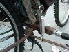
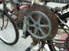
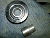
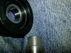
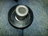
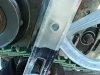
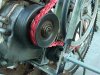
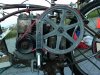
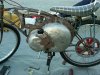
Go to MTD snowblower and you can get a metal flat ideler pully for the same snowblower that decotherd's engine come off of.
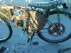
It a model 181 single stage snowblower. I typed in Murray 181 and it come up and went from there.
I thought you had it right or i would have sent you the site. If you would have a way to spin a roller skate or skate board wheel you could put a grouve in the center with a file or even a wood lath tool...............Curt
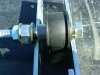
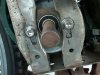
Looked it up here you go. Its the size you are looking for the snowblower had a 1/2 inch belt the pully is under 2" and has a 3/8" bolt hole. The oridgonal was metal but the new one looks plastick of some sort. http://www.ereplacementparts.com/flat-idler-p-961236.html
I have one someplace in the shop i just took it off last fall when i sold the motor to decothered
It a model 181 single stage snowblower. I typed in Murray 181 and it come up and went from there.
I thought you had it right or i would have sent you the site. If you would have a way to spin a roller skate or skate board wheel you could put a grouve in the center with a file or even a wood lath tool...............Curt
Looked it up here you go. Its the size you are looking for the snowblower had a 1/2 inch belt the pully is under 2" and has a 3/8" bolt hole. The oridgonal was metal but the new one looks plastick of some sort. http://www.ereplacementparts.com/flat-idler-p-961236.html
I have one someplace in the shop i just took it off last fall when i sold the motor to decothered
Last edited:
")
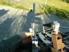
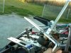
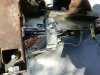
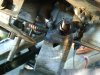

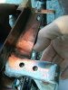
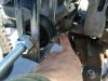
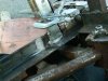
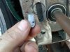
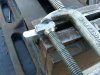
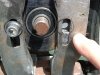
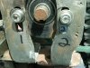
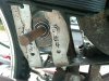
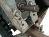
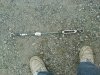
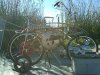
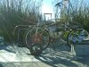
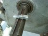
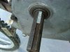
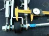
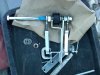
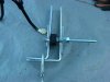
 Just realized that after trimming down the idler pulley bracket as planned, I as planned might or might not use the left over pieces to make other parts for the bracket. Those would be a shim that once the idler is in the position to tension the belt fully, these would prevent the bolt from slipping back down. The external star tooth washers would not be necessary and a split lock washer used instead.