Charging

GoldenMotor.com

Agreen

Member
Feb 10, 2013
792
11
18
Southeastern GA
Possible, but not practical. You would need to rectify the output to DC first. A full wave bridge rectifier would give you a scallop-wave output that would need to be filtered. A filter network can minimize the amount of waviness, but you'd need a regulator to keep the voltage output constant as engine speed changes. Once all the losses are considered, you'd end up with a charger capable of about 50mA at best. You would have to limit the current output, otherwise the coil would burn up in no time.

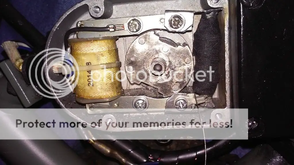
There was a 12v coil that could be bolted right beside the ignition coil. Can't remember where I saw it for sale, but that one wouldn't steal power from the ignition coil (which is puny enough without an added draw).

So the short answer is: possible, not really worth it, maybe if you used a separate coil.
 

Davezilla

New Member
Mar 15, 2014
2,705
10
0
San Antonio Texas
I agree... possible but not practical... I've seen those 12v coils before on ebay, they bolt up on the opposite side of the mag coil and use the mag rotor for a magnetic field so they don't steal any power from the ignition system. Last time I looked they cost around $30 and the guy does sell them for charging small batteries as well as providing a 12 volt source on the bike, I'll post the link if I can find it...
 

DaveC

Member
Jul 14, 2010
969
1
18
Boise, ID
If you can figure out the pins and circuit then one of these;

http://www.ebay.com/itm/12V-4-PIN-A...0CC-/311220973253?hash=item4876372ec5&vxp=mtr

This comes with wiring and one of these;

http://www.ebay.com/itm/12V-10AH-Re...als-/252091389995?hash=item3ab1d1582b&vxp=mtr

The regulator is to prevent overcharging the battery and the battery makes it so you have steady lights even at idle. You would need to find someone, most likely here, to design the wiring you need to make it work. If you can find a local guy to help that'd be even better. It's not all that difficult and you could run just about as many lights as you want scratg
 

DaveC

Member
Jul 14, 2010
969
1
18
Boise, ID
Perfect. So all I need to do is hook all this up and it will be able to charge? Will it put much load on the engine? I don't know much about the regulator-but will this one work?

http://www.radioshack.com/radioshack-12v-fixed-voltage-regulator-7812/2761771.html

If not, how do I wire it up?
...oh...umm...ahh... no hehe. That will not handle the amperage. One meant for a motorcycle or car is what you need. One off an old 12 volt car that works is a good start. Check out an older car scrap yard, they should have one around. Then look around on the internet for a wiring diagram. There's only 3 wires to deal with, even a 101 book on electronics should have a diagram.
 

rocksalt27

Member
Oct 24, 2013
121
15
18
Portland, ME
Ok, well, my goal here is just to make a trickle charger. It does not have to be fast at all. So any ideas there? Could I use the auxiliary magneto wire with a resistor on it? What's that wire meant for anyway?
 

Agreen

Member
Feb 10, 2013
792
11
18
Southeastern GA
Snake oil.

Really, it's a gimmick at best. The white wire is for marketing purposes. The kits sell better because they can advertise that you can run lights off of it.

To explain how it works will take some understanding of electric generators and electronic circuits.

First off, there's a magnet that the engine turns. It's a plain jane permanent magnet. Ever seen "magnetic lines of flux"? Magnets create invisible lines of magnetic flux. This can be seen and proven by placing ferrous (iron) shavings on a piece of paper, then placing the magnet underneath. You will see the shavings create actual lines between the north and south poles.

When the magnet rotates, it also turns the flux lines. When the flux lines pass over a wire, it induces a voltage in the wire. Coil that wire up and the flux cuts through a whole bunch all at once, inducing an even stronger voltage. Give the wire a path (as in through a circuit, then back to the coil) and current will flow.

Now, the " 6v" white wire is just a little wire that's hanging out of the middle of the coil. If you put a load on that wire, you create a parallel path, meaning the current can find another way to go. This guy back in the day named Kirchoff figured out that if parallel paths are made, the voltage won't change on the individual branches, but the current on each branch in the parallel circuit is cut down.

What that means is that if you use the white wire, you will lose current to the CDI. The output of the CDI is too low anyway, so you don't need to do anything to reduce it any more.

Now, if you use that "12v" coil, it could work without added drag on the ignition system. It will, however, add drag to the engine. Yes, an alternator on a car adds drag to the car's engine too. You just never realize it because it's never off.

To use the "12v" coil, you will have to rectify and regulate the output. See, as the "north" pole of the magnet passes by perpendicular to the coil, it produces a max positive voltage. The more it turns away from perpendicular, the weaker the generated voltage gets, until it's parallel with the coil and the voltage output is zero. Here comes the south pole, and as it approaches the coil perpendicularly, it generates a negative voltage! The cycle continues as it continues to rotate. This produces an AC sine wave. LEDs can't use AC, since they require DC. I mean, you *could use AC, but it would flash. LEDs are "Light Emitting Diodes". A diode only let's current flow in one direction, not both.

So how do you make the cyclic sine wave of AC to DC? Easy. A collection of 4 diodes arranged in what's called a " full wave bridge rectifier ". Diodes operate like electronic check valves. So what you end up with is a bunch of positive pulses. Imagine that sine wave with all the negative humps flipped up to positive humps.

But that's not very DC. DC is a constant voltage, not an up and down. And even then, the voltage output is uncontrolled. As the speed increases, the voltage output increases too. So at idle you'll get next to nothing, and you could get something like 20v at full speed.

On top of that, you'll need to limit the amount of current output. Say you hook it up and the system draws more current than those little coil wires can handle. Then those wires would glow red hot and burn up. Then you're having to replace the coil a lot.

So, you'll need
-separate coil
-rectifier
-filter
-voltage regulator
-current limiter

I know my electrical and electronic circuits pretty well, but I'm not good at designing them. So... sorry I can't help there. If it's broke, I can fix it. I can tell you how it all works. I just can't design one to save my life!
 

rocksalt27

Member
Oct 24, 2013
121
15
18
Portland, ME
Ay carumba. That is somewhat complicated. I guess I'll just use my solar panel! I have the little one from harbor freight. Does it need a limiter like a Zener maybe?
 

Agreen

Member
Feb 10, 2013
792
11
18
Southeastern GA
Even I have limited knowledge to build such a circuit, but I would know it if I see it. I'm doing a search now to see what I can come up with. A simple full wave rectifier is easily built, so that's not an issue. Even an R/C filter network is pretty simple, so that I'm not too concerned with. I'm looking up 12v regulators now to see what I can find. Something low output that limits the current output to, say, 0.5A would probably be sufficient. If I can find all this stuff, you may be in business. Put it all together in a sealable hobby box and it may work. I'll just have to continue searching now, because this does kind of pique my interest a little.
 

Agreen

Member
Feb 10, 2013
792
11
18
Southeastern GA
http://www.ebay.com/itm/12V-DC-Gene...37a723e&pid=100005&rk=2&rkt=2&sd=261869425349

That's the 12v add-on generator I have been referring to. Now, it does say 12v DC generator, but I can tell you it's not. So I'd have to buy one, hook it up, measure the idle and full speed voltage and frequency. THEN and only then will I know what kind of circuit to build.

I did just download a sweet circuit-building app that lets you tinker with it before putting it together for real.

Unfortunately, looking at it now, it feels like it's going to cost a lot for something as silly as a 0.5A generator. Just the additional coil costs $30, and then you have to buy all the extra BS to make it put out the proper voltage and current (one that won't burn things out).

Then again, I feel as though building a laminated steel body and wrapping it in magnet wire will probably cost around $5 total, and it would be easy to build as well. Paying $30 for a pre-made lie is absurd.

I may do some tinkering soon...
 

egjsc

New Member
Jun 8, 2015
27
0
0
Oxnard,CA
Cool let us know what you find works best. There are so many avenues and route's to take. My first thought was/is led all the way but the further i look into developing a proper, reiable, Cheap circuit (thoes words do not go together!) Ac lighting is looking alittle more practical but im not sure what what my "12 volt coil" can output lumen wise, i returned a "generator coil" with 32g mag wire. Not much room for more turns especally when using a larger mag wire. All the calulaters ive found need an input of the stregth of the magnet which i have no idea on how to measure.
 

Agreen

Member
Feb 10, 2013
792
11
18
Southeastern GA
Well, I never did buy one of those, but I did decide to roll my own.

The results are really not that impressive.

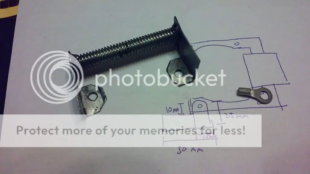
I started by building the "frame". I need some kind of iron core, so this is what I came up with:


I then wrapped magnet wire around the core and wrapped it in fiber tape. 30yds total.


Once installed, I tested AC volts. So far I got 5v by free revving it in the driveway. Not looking good.


I wonder if that "12v coil" will get anywhere close to the claim?
 

Agreen

Member
Feb 10, 2013
792
11
18
Southeastern GA
1.2 volts ac at idle is weak. Maybe i can step my coil game up and try for something better, but it's going to have to be over12v ac at least. It has to get rectified, filtered, and regulated, which will require some thought.


I think i may have a solution though! I have a pull start on my engine. I want to use that to my advantage. If i can get some rare earth magnets on the pull start bell, i can make a series of coils around the pull start cover. With all the coils being in series and several magnets, it's bound to be a strong output.
 

Agreen

Member
Feb 10, 2013
792
11
18
Southeastern GA
I'm still in the planning phase of this next attempt. I have ran through a few ideas of what I want to try.

The basic idea is that I'll use (as stated before) rare earth magnets like neodymium, on the outside of the pull start "bell". It's the part that bolts to the rotor magnet. I'm considering keeping it simple, and making it a 4 pole single phase generator. That would mean I would have 4 magnets (arranged North, South, North, South in a clockwise direction on the rotor) and 4 coils on the outside of the casing. Probably just bolts that I could drill holes in the case and snug down, then wind the magnet wire around.

The idea is that more poles and more coils (bigger stator) will make more power. I can get an even higher output if I made a 3 phase generator. Then I could use a 6-diode full wave bridge rectifier, leaving me with a more stable input to a voltage regulator.