
MikeJ
New Member
Hi Everyone -
I think an analog tachometer for a Chinese engine can be done using off-the-shelf parts. I will spare everyone the long, gory details, but the bottom line is you have to use that one controversial component of every Chinese two-stroke...
The White Wire.
That's right, the White Wire. Disregard trying to use the spark plug wire if you want to use an analog tach. You need an analog signal, specifically the sine wave voltage that appears on the white wire. The sine wave frequency and voltage varies with engine RPM. Those are the keys to using an analog tach.
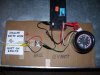
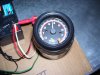
Get the tach of choice at the local auto supply store. The tachometer must say to connect it to the distributor or coil of the car; most tachs do. I purchased one that would look good on a bicycle for about $32 from an auto parts chain store and I was out the door. It even has a light to illuminate the face of the meter for night riding.
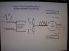
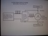
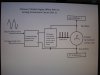
The provided diagrams should be fairly self-explanatory. The sine wave voltage coming out of the magneto gets rectified into TWO positive-going pulses. The tach has a selector switch for 8, 6, and 4-cylinder engines. Set the switch to only "4". This allows the tach to sense the pulses fed into it and display RPM directly onto the meter face. There is no other alteration to the purchased tachometer.
The battery is a 3.3 Amp-hour battery from a local hardware store. A charger had to be purchased as well. If you have a 5000 cranking amp 12 volt truck battery, you can use it. The tach draws only 35 milliamps; it won't hurt either battery if wired correctly.
My test frequency of commercial electricity is available at 60 Hz (common knowledge). That is also the same frequency as a Chinese engine magneto output at exactly 3600 rpm. By using this, I proved that the circuit you see worked at this one frequency, simulating an engine spinning at 3600 rpm. The voltage being fed to the rectifier was 10 volts AC, right in the middle of the magnitude range produced by the magneto at operating rpm.
There is still testing to be done, to include with a real engine. Just because it works on a test bench does not guarantee success in the field. But it is a good indication of success.
If you are interested in pursuing this, please do so. Share your findings with the rest of us; I probably will need a few weeks or so of more time for testing.
MikeJ
I think an analog tachometer for a Chinese engine can be done using off-the-shelf parts. I will spare everyone the long, gory details, but the bottom line is you have to use that one controversial component of every Chinese two-stroke...
The White Wire.
That's right, the White Wire. Disregard trying to use the spark plug wire if you want to use an analog tach. You need an analog signal, specifically the sine wave voltage that appears on the white wire. The sine wave frequency and voltage varies with engine RPM. Those are the keys to using an analog tach.
Get the tach of choice at the local auto supply store. The tachometer must say to connect it to the distributor or coil of the car; most tachs do. I purchased one that would look good on a bicycle for about $32 from an auto parts chain store and I was out the door. It even has a light to illuminate the face of the meter for night riding.
The provided diagrams should be fairly self-explanatory. The sine wave voltage coming out of the magneto gets rectified into TWO positive-going pulses. The tach has a selector switch for 8, 6, and 4-cylinder engines. Set the switch to only "4". This allows the tach to sense the pulses fed into it and display RPM directly onto the meter face. There is no other alteration to the purchased tachometer.
The battery is a 3.3 Amp-hour battery from a local hardware store. A charger had to be purchased as well. If you have a 5000 cranking amp 12 volt truck battery, you can use it. The tach draws only 35 milliamps; it won't hurt either battery if wired correctly.
My test frequency of commercial electricity is available at 60 Hz (common knowledge). That is also the same frequency as a Chinese engine magneto output at exactly 3600 rpm. By using this, I proved that the circuit you see worked at this one frequency, simulating an engine spinning at 3600 rpm. The voltage being fed to the rectifier was 10 volts AC, right in the middle of the magnitude range produced by the magneto at operating rpm.
There is still testing to be done, to include with a real engine. Just because it works on a test bench does not guarantee success in the field. But it is a good indication of success.
If you are interested in pursuing this, please do so. Share your findings with the rest of us; I probably will need a few weeks or so of more time for testing.
MikeJ


")