

modified cdi and cr 80 coil
- Thread starter damo99
- Start date

That's what we're saying - but we need pics of the guts of one to be able to replicate it. I've ID'd half the parts, but I need better pics to both verify and get the rest of the resistors and diodes, capacitor and thermistor.
The diodes are probably all 1N4007This is the best I've got so far from that pic, though some can possibly be assumed - there's still quite a bit that needs done. Resistors to be labeled, capacitor to be labeled, thermistor to be labeled, and diodes to be confirmed.
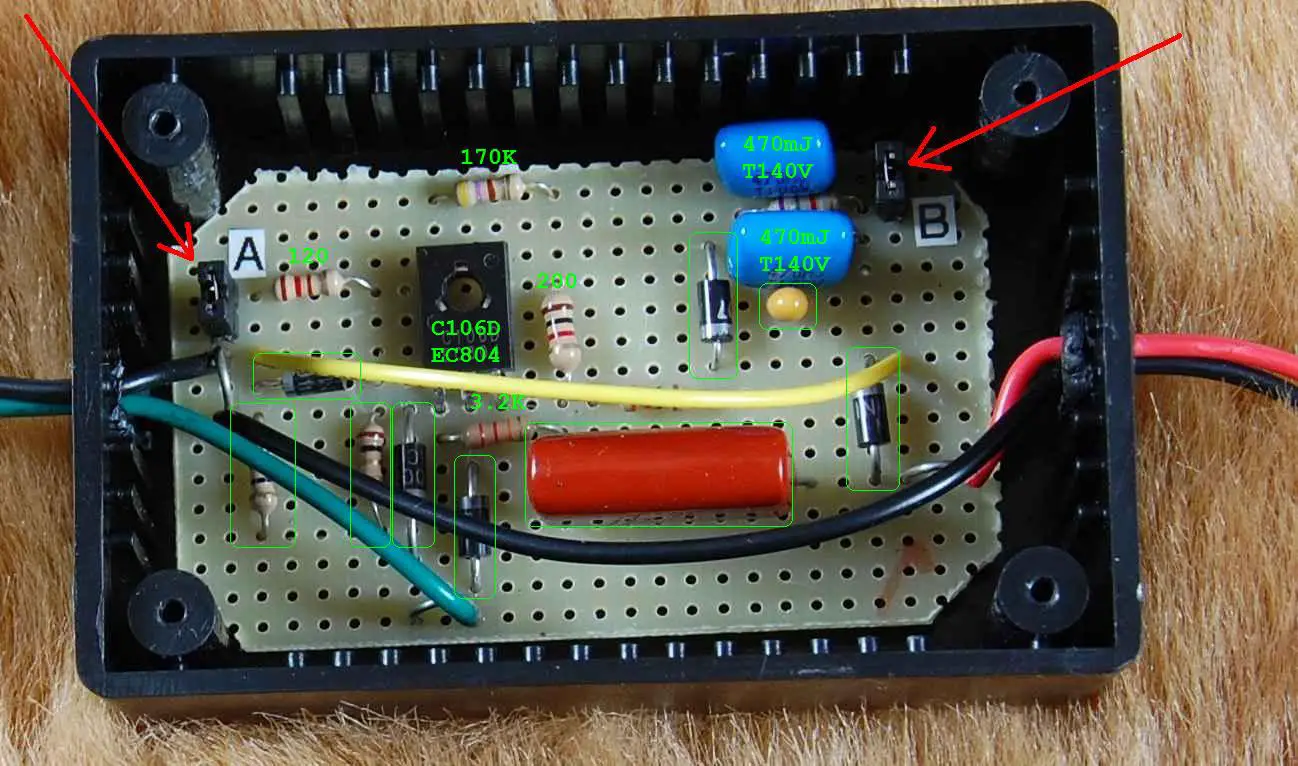
The resistor labelled 170K , first band is yellow(4), so should be 470K, although 3rd band looks brown to me (470 ohm)
Resistor next to SCR (brown black red) is 1K
Brown black gold resistor (7 o'clock from SCR) is 1 ohm
Thanks Rohmell - I'll edit and update the pic. My eyes are so bad, I have to keep my resistors in labeled bags. xDThe diodes are probably all 1N4007
The resistor labelled 170K , first band is yellow(4), so should be 470K, although 3rd band looks brown to me (470 ohm)
Resistor next to SCR (brown black red) is 1K
Brown black gold resistor (7 o'clock from SCR) is 1 ohm
Could you possibly take a picture of the bottom of the board? This would help greatly in making a schematic of the unit.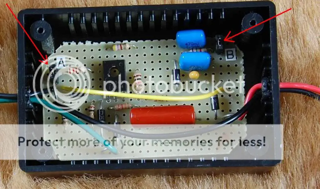
Heres the inside of the cdi, if some one that has one of these will make a wiring diagram and list the parts. $75 for this is intense i wonder what he pays his employes...

Wow looks great guys! I might just hold off building one until you fully crack this one! Keep it up!~
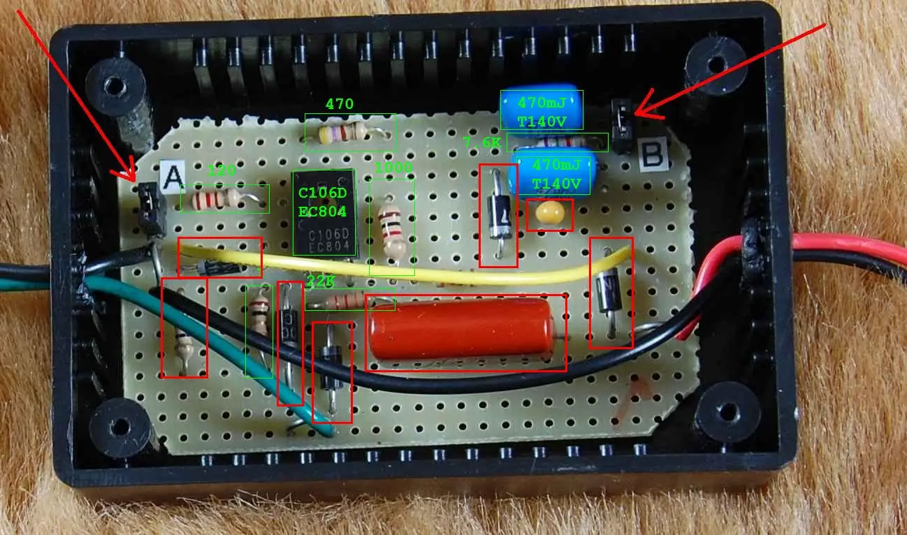
7.6K ( between two blue caps) might actually be 750 ohms (violet,green, brown)
this is a more likely value to work with the adjacent capacitors for adjusting the timing curve. That, and 7.6 is not a standard EIA value for resistors.(well 768 is, but we are dealing with 4 banded resistors, so look in the 2,5 and 10 % columns)
(Electronics Reference: EIA Standard Resistor Values)
Last edited:
I think you're right on that one rohmell. Sure looks blue to me, but green adds up better. 
Of course, these pics were taken to show jumpers and headers, not to read components. I'd still really like to see some even more high res pics.
Of course, these pics were taken to show jumpers and headers, not to read components. I'd still really like to see some even more high res pics.
The 22K resistor, the last band looks kinda brown to me, so perhaps that is a 220 ohm resistor, again more likely to be that value and connected in the gate circuit of the SCR than a 22K resistor.
BTW, thanks for all of your help labeling the various parts.
BTW, thanks for all of your help labeling the various parts.
Like I said, my eyes are bad, and these pics suck. xD
I'm going both off a printed page and a full screen here, and can't hardly read half of the bands.
Not a problem at all - it helps to have a visual progress bar so we know what we've got left to do. Though you're probably right about the diodes, I do want to hold off on labeling them until we're positive. I'm glad you've jumped on board with this one Rohmell - it helps a lot!
Editadd:
Actually though, wanna take a second look at the 220/22k? Last band looks orange on both screen and page.
Last edited:
On one diode I see 1N, and on another I see 00, and on a third I see 7, so it would make sense to be using the commonly available 1N4007 diode, which is rated at 1A, 1000V.
But of course, we won't know for sure until someone who has one of these units lets us know for sure.
But of course, we won't know for sure until someone who has one of these units lets us know for sure.

Awesome, Thud! I have it bookmarked.that really is not much different than this one:
Transistor Ignition Modules
If you would lend your expertise to another thread it would be appreciated... and suggestions on this?
http://motorbicycling.com/f3/2-stroke-electric-starter-31050-4.html#post299892
It is different in that it uses a bipolar transistor (TIP42C) instead of an SCR, and a Hall effect sensor to detect when a magnet passes by to create a pulse, plus the kit supplies you with a magnet to mount to a flywheel, etc.that really is not much different than this one:
Transistor Ignition Modules
Plus, external power is needed to operate it.
Yes, absolutely. In fact, there are companies that will make PCBs for you, all you have to do is create the PCB using software that you download from them, email the file to them, they make them and ship them out to you.
Like this:
ExpressPCB - Free PCB layout software - Low cost circuit boards - Top quality PCB manufacturing
Like this:
ExpressPCB - Free PCB layout software - Low cost circuit boards - Top quality PCB manufacturing