

Thanks cannonball2. I will post some more as my build progresses. I can unfortunately only work over the weekends, as that is the only time I can get free.
Weed Eater Friction Drive Bicycle
- Thread starter landuse
- Start date

From seeing CB2s build post a while back, I went with a scissor lift on my Ryobi weed eater build as well. So far, it is working great. I have it run to a bicycle brake lever on my bars, mounted backwards. I am using regular bicycle cables that I picked up from the same bike shop I got the levers from. The 30cc Ryobi is not too heavy, so it lifts fine.
Clutch left, throttle right, thumb activated:

Scissor clutch arms (I set mine up to pull on both sides instead of just the motor side):

BTW, I love your heavy duty brackets. I really need to get a welding rig. Hand cutting aluminum bar stock got real old, real quick, lol.
Clutch left, throttle right, thumb activated:
Scissor clutch arms (I set mine up to pull on both sides instead of just the motor side):
BTW, I love your heavy duty brackets. I really need to get a welding rig. Hand cutting aluminum bar stock got real old, real quick, lol.
Thanks for the pics maurtis. I like the double scissor arm setup you have. How did you connect the two cables from either side to run on a single cable to the clutch lever? What type of attachment did you use? Also, does the cable not touch the wheel as it runs to the join?
What cc is your Ryobi?
Edit: I just read your build thread. Good work!
What cc is your Ryobi?
Edit: I just read your build thread. Good work!
Last edited:
It is a 30cc Ryobi, the TP30 from a pole saw. I think it is pretty similar to the SS30 string trimmer motor.
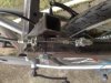
The cables have plenty of clearance around the tire, you can kind of see it here:

To attach the cables together, I used a wire guide from Home Depot and bent it out to match the angle of the clutch legs. Then drilled two holes in it to pass the cable from the clutch lever through. The clutch cable is fastened with one of those crimp down aluminum cable stops, from Home Depot as well. I am sure there are better ways to do this, this is just what I had on hand, lol.

My setup would have been a lot cleaner except the clutch cable would get hung up on my seat post and would lock into place. If I moved where the cables joined closer to the wheel, I would lose cable clearance. This is why there is an aluminum plate keeping the cable join off of the seat post.
Now that I look at it, I can move the join closer to the front of the bike and eliminate the need for the plate guarding the seat post, duh. I will need to pick up a new bike cable since the one I am using has been trimmed too short, but that is only another $3...
The cables have plenty of clearance around the tire, you can kind of see it here:
To attach the cables together, I used a wire guide from Home Depot and bent it out to match the angle of the clutch legs. Then drilled two holes in it to pass the cable from the clutch lever through. The clutch cable is fastened with one of those crimp down aluminum cable stops, from Home Depot as well. I am sure there are better ways to do this, this is just what I had on hand, lol.
My setup would have been a lot cleaner except the clutch cable would get hung up on my seat post and would lock into place. If I moved where the cables joined closer to the wheel, I would lose cable clearance. This is why there is an aluminum plate keeping the cable join off of the seat post.
Now that I look at it, I can move the join closer to the front of the bike and eliminate the need for the plate guarding the seat post, duh. I will need to pick up a new bike cable since the one I am using has been trimmed too short, but that is only another $3...
Thanks maurtis. Having the clutch cable on both sides must make it easier to lift the engine. I will see if I can incorporate that into my build as well. I just find it frustrating that I always have to wait for the weekend before I can do anything. I just don't have the time anywhere else.
If you are using steel, 3/16 flat stock is plenty strong to lift with a single strut. Makes it simplier to fab. The aluminum build probably benefits from two struts. Remember the tire supports the engine when down, strut supports only when lifted, though does add some stability. I do leave my engine lifted when not in use so as not to flat spot the tire. Both of my full susp.. MTBs use only a single sided engine support. I really dont know what the spring down force is but I imagine the lift is atleast 50lbs, engine and spring combined. Your build are using only a 6-7lb engine + whatever spring force you have. Wont take much to lift em.
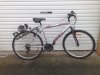
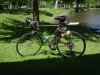
OK, so I pretty much finished my bike this weekend. There are one or two things that still need to be done like fixing the kill switch to the frame, and neatening up some of the cables. I also have to do the scissor clutch, lie maurtis has, as I didn’t have time to do it this weekend.
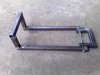
I first welded the metal strips I am using as a motor mount to my frame. It was a bit of a pain to get everything lined up, but I got it done in the end. I also fixed my frame to the bike, so everything was lined up. I then mounted the engine, cut some grooves in the foot peg, and added the springs and turnbuckles.
The springs worked better than I had hoped. I had bought much longer springs originally thinking that the whole frame would sit higher than what it does, but fortunately I had the shorter ones lying around. I just drilled a hole on either side for the spring to hook onto.
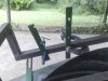
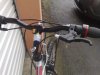
On Saturday I went to our local bicycle shop, and bought some more brake levers for my throttle and clutch. I mounted then on the handle bars opposite to what they should be, so that I could operate them with my thumbs. I had also bought some cheap brake kits, so I had a few pieces that I could use to set the accelerator up. I took a pic of where I connected the two cables. I hope it works out OK.
I lengthened the kill switch, so it reaches the handles now. I must just buy some more zip ties to neaten it all up. By this time it had started raining, and I wasn’t able to take it on a test run, but this evening when I get home (if it isn’t raining) I am going to give it a run.
I will let you know how it turns out
I first welded the metal strips I am using as a motor mount to my frame. It was a bit of a pain to get everything lined up, but I got it done in the end. I also fixed my frame to the bike, so everything was lined up. I then mounted the engine, cut some grooves in the foot peg, and added the springs and turnbuckles.
The springs worked better than I had hoped. I had bought much longer springs originally thinking that the whole frame would sit higher than what it does, but fortunately I had the shorter ones lying around. I just drilled a hole on either side for the spring to hook onto.
On Saturday I went to our local bicycle shop, and bought some more brake levers for my throttle and clutch. I mounted then on the handle bars opposite to what they should be, so that I could operate them with my thumbs. I had also bought some cheap brake kits, so I had a few pieces that I could use to set the accelerator up. I took a pic of where I connected the two cables. I hope it works out OK.
I lengthened the kill switch, so it reaches the handles now. I must just buy some more zip ties to neaten it all up. By this time it had started raining, and I wasn’t able to take it on a test run, but this evening when I get home (if it isn’t raining) I am going to give it a run.
I will let you know how it turns out
Attachments
-
 171.4 KB Views: 379
 -
 143.4 KB Views: 693
 -
 128.1 KB Views: 367
 -
 184.1 KB Views: 932
 -
 112.5 KB Views: 398
And some more......
Attachments
-
 149.6 KB Views: 418
 -
 129.9 KB Views: 7,689
 -
 108.5 KB Views: 362
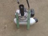
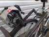
Nice set up. If you want to move the engine fwd some redrill the holes in the mount where it attatches to the clamp and shorten the overhang. Since you have cut the cooling shroud the fan really no longer cools the engine. I would remove the rest of the shroud to allow the air flow to reach the cylinder.
Thanks cannonball!! You say that the 'fan' no longer cools the engine. What fan are you refering to? All I removed was the section of the housing that had the recoil starter in it. Could you maybe explain. Sorry, but I am new to these engines.Nice set up. If you want to move the engine fwd some redrill the holes in the mount where it attatches to the clamp and shorten the overhang. Since you have cut the cooling shroud the fan really no longer cools the engine. I would remove the rest of the shroud to allow the air flow to reach the cylinder.
The impeller blades on the flywheel forced air up the shroud and across the cylinder then out the back cooling the engine. It has been kown that these engines will cool ok in free flow, but you have it pertty much blocked now.
Thanks cannonball. I will have a look at that.The impeller blades on the flywheel forced air up the shroud and across the cylinder then out the back cooling the engine. It has been kown that these engines will cool ok in free flow, but you have it pertty much blocked now.
I was all exited when I got home last night to try my bike out. I hopped on, started pedaling with the choke on till it wanted to start and then took the choke off. It started fine, but I just had no torque at all. It was really dissapointing. When I turned round at the end of the street to come back home I had a bit of a downhill, so that went fine.
When I got off the bike and had a look at the motor, I saw that the roller had come loose, and could rotate on the motor shaft a bit. This was probably causing the terrible torque. I think the roller is also too big for my motor. It is a 1 1/2" foot peg. I think I might try something with a smaller diameter.
I also smelled something like burning rubber, but it wasn't the tyre at all, it was the engine. I also saw a wisp of smoke come from the engine. Do you think that the loose roller could have overheated something on the engine to make that smell. The tyre still looked good.
It was a dissapointing first run, but I will get her right soon.
I was thinking of going with the smaller roller for more torque. I am going to secure the peg again and see if that was the problem with the poor response. If not, then I will go with the smaller diameterMany DIY guys have bolted a BMX foot peg onto the weedwhacker as a friction roller.
The smaller the roller diameter, the more the low end response.
That version of a "Ryobi" is not as powerful as the original 31cc. My one weedeater build with one ran a 1.5" well. I lost some hill climbing but general performance was better other wise as it cruised at lower rpms. All engines are different, you may have to experiment with different sizes. Thats why I favor oak, they are tough, cheap and quick to make. But hard to make much under 1.25". Did you remove the shroud? If not you were probably overheating the engine hence the smell and smoke.
The build looks great, nice and sturdy. I bet you could throw a seat over it and carry someone to help provide downforce! lol
On my 30cc Ryobi build, I used a bike peg with a 1.25" outer diameter, which seems just about right for my 200 lbs. I also had an outer sleeve over the peg for a while to get additional traction, but it bumped the diameter to a little over 1.5", which was too large. I would lose speed going uphill (slight hills around here). Taking the sleeve off, on hills I can slowly gain speed, or at least maintain my current speed, and still have a decent top end on flats.
So now I need to come up with a way to increase traction on my roller without increasing the diameter too much. Thinking the JB Weld/sand coating will be this weekend's project.
You also might want to look at your carb mixture. Mine came pretty lean from the factory, and to adjust the mixture screws I had to purchase a "double d" adjusting tool. That freed up a little more power after tinkering with the mix, but it took a while to get it right.
Traction is the holy grail of FD, how to get it with out increasing tire wear to an un acceptable point. With good down force I have found smooth rollers drive well with the least amount of wear, but dont handle wet vey well. I have "rain roller" bonded with 50 grit water proof sanding belt, it will drive you through any water you can find, but is very unfriendly to tires, so its an emergency get home in the rain use only. I went the route with epoxy/sand coated rollers and they didnt last. JB weld may be better but it is an epoxy base. If you dont have a good deal of tire deflection, you will have slippage. With the WE engines being so light they require a good deal of spring loading, if you are not seeing the tire flattened under the roller a good bit you are gonna slip. Tire design is also a major factor. The best tire I have found is a 2.125 cruiser tire with only about 30-35 lbs of pressure. They flatten nicely under the roller to drive the tire all across the tread. The smaller 1.95 down tires crown a lot and limit the drive patch generally. I was able to easily fit the 2.125 tires in place of the 1.95s on my Mongoose MTB. This bike now has over 2K miles with one drive tire change around 1200mi. Its a trade off with a WE engine being so low on hp. You will have to balance down loading, tires, tire pressure and roller design to optimize it. I have the advantage of running 100cc torque monsters that really could care less what you do to the mix. The WE will require some finesse.
Thanks for the tips! I am using the Bell Streamliner cruiser tire, which is nice and wide and has a good tread pattern. BUT, I am still running at 40 psi. Let me crank that down to 30 psi and run with shorter springs and introduce turnbuckles to tune the downforce.
Since I did away with the support bearing, I was hoping to not have to crank it down too hard since I did not want to kill the motor bearing too quickly, so I will work on finding that balance.
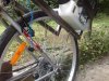
You can tell from the wear on my roller that I am not making full contact with the tire...

Thanks!
Since I did away with the support bearing, I was hoping to not have to crank it down too hard since I did not want to kill the motor bearing too quickly, so I will work on finding that balance.
You can tell from the wear on my roller that I am not making full contact with the tire...
Thanks!
Last edited:
Hi Landuse,
Looks like your build is coming along nicely. It certainly should be sturdy enough!
Do you have the "clutch" (motor lifter) setup yet? I don't see it in the pics. I like the idea of the scissor lift the other members have mentioned and shown.
If you are going to have the "rack" on both sides of the rear tire, you might want to get a bearing to support the far end of the drive roller/shaft.
That will take a lot of stress off the motor bearing. I get bearings from Blain's Farm & Fleet for 8 bucks.
I've been riding my 25cc Homelite motorized 1973 Schwinn Continental for 4 full years. I know I have more than 10,000 miles on that motor.
Here's some pics. I've posted others here if you search. I'll have to upload some more recent ones.
This one:
http://motorbicycling.com/attachments/f3/10238d1246421161-my-frame-broke-motor-side.jpg
shows how the pivot is mounted to only the seat stays, and that has proven to be plenty sturdy.
You can also see my friction roller homemade from a hockey puck. The rubber grips well on the rubber tire with very little wear.
Keep us updated on your progress.
Attachments
-
 130.6 KB Views: 371
Thanks A_dam. I haven't done the 'clutch' yet. I will definately have to do it soon, cos trying to move the bike around without the engine lifted is a real pain. I basically have to raise the back wheel and walk with it like that. I will do it soon hopefully.
I like the look of your setup you have. If yours works so well for you, I am sure I will be able to get mine working too. I have also been toying with the idea of a bearing support, but I will see how things work out.
I will definately keep you updated on the progress.
Edit: Could you maybe tell me what you used to lift the engine off your back wheel. Somepics would be nice if you have. Thanks!
Last edited: