The Raven

GoldenMotor.com

16v4nrbrgr

Active Member
Mar 17, 2012
1,728
4
38
North Bay


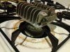
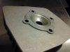
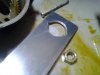
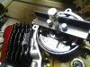
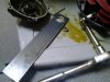
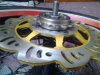
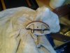
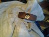
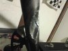
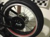
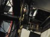
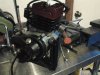
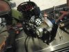
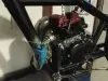
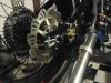
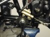
Plate reinforcement for the bottom bracket frame union to join the bottom tube to the seat tube before putting the new bottom bracket in. Using a hole saw for the new bottom bracket took out a lot of material tht needed reinforcement. I eventually cut it shorter so I wouldn't have to weld at the edge of the bracket, and the joint would fillet smoothly.

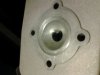
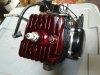
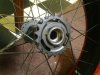
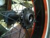
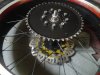
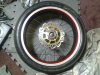
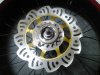
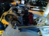
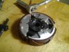
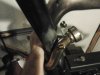
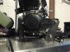
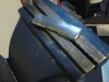
I welded coin shaped pieces on the useless holes on the frame and welded bungs into the holes to be used for the engine mount, same as those used on the old "happy feet" engine mount. On the bottom I used rosette welds instead to fill the holes just to try out my new welder. :p

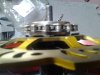
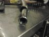
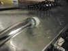
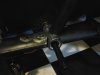
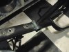
I'm confident that the welded area will be very strong. I had to clean up a touch of the threads inside by using a tap as a thread file scraper where I melted through a bit and the union hasn't hardened like the original brittle joint that killed my hole saw. TIG localizes the heat affected zone as you can see from the remaining paint on the frame unaffected, and anneals the area similar to rosebud torch annealment for chromoly joints.

The trick to keeping everything aligned and not stressed is working fast while its hot and moving back and forth and alternating your welds to move the heat all around the area.

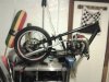
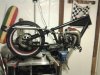
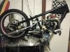
It's not my prettiest work, but now my frame isn't swiss cheese! :)
 

Attachments

Last edited:

16v4nrbrgr

Active Member
Mar 17, 2012
1,728
4
38
North Bay
The stock head isn't too bad, needed lapping since they turned it concave on the lathe and it woulda leaked from around the bolt holes, so after getting it completely flat and smooth, which required taking a lot of material off, like half a millimeter until it was flat...

Ground off the casting roughness lightly

Swirl polished and smoothed edges of squish ring.

I had accidentally dropped the motor last spring and had broken a fin on the head, so as a permanent fix to the bolted attachment I brazed the head and then cleaned it up a bit. The rest of the head and flatness were unaffected, checked afterwards.

I'm using a different E3 spark plug since it fits into the head right, it's the equivalent to the NGK-R "car plug" they sell in the small engine section of Oreilly. It looks to have the highest compression because it has so much electrode and the reviews for E3 are good. We'll see, NGK's are cheaper if it doesn't like it.

Oh, by the way, the cylinder and piston are very nice inside, didn't see any swarf or sand or anything and it pumps smooth, dripped some mobil1 on the cylinder so the startup won't score anything the first time.

Red represents the blood I pour into each and every one of my projects, lol!xct2
 

Attachments

Last edited:

Crazy Horse

Dealer
Feb 20, 2009
1,153
3
36
USA
Excellent fabrication work you've been doing there 16v.

I really like the Cafe style you given your build, Kudo's bro.

The fairing is bada$$, as well as the K10 forks.

Nice custom jackshaft. to boot!!!

C.H.
 

16v4nrbrgr

Active Member
Mar 17, 2012
1,728
4
38
North Bay
Thanks Crazy Horse,

The cranks are actually just the SBP wide kit with some unicyle cranks and a cheap rear 3 speed freewheel flipped around. I figured if I had this, a shift kit or aux drive would be easier later. Right now it's to make the bike legal, but I scounged up a 16t rear freewheel for the pedal side so it should have decent takeoff gearing like a moped.
 

16v4nrbrgr

Active Member
Mar 17, 2012
1,728
4
38
North Bay

Took a sturmey sprocket with stripped nubs, stripped them out fully with a file, and welded on both sides some M6 nuts. The brake rotor will attach to this hub, and it's tacked to the wheel hub with 3 tacks.


Same deal here except this 18t Sturmey will be squeezed inside the stock rag joint as a hub damper.


You can't change spokes unless you grind the tack welds off, but this OCC wheel will hopefully be replaced by a mag wheel before I have to do that.
 

Attachments

Last edited:

16v4nrbrgr

Active Member
Mar 17, 2012
1,728
4
38
North Bay

Made a Thor tool for counterholding the crank, insert bolts next to the NApa 17mm socket.

Here you'll see what I mean.

Then made a Morini clutch tool, 2 x M5x0.80 distanced 9/16 from the center with a M8x1.25 (could be any big bolt) to push against the crank snout. Clutch came off with a POP!

I think martin and slater runs the motors on a dyno for quite a while at their factory, because the transmission casing has a lot of clutch and bell dust.
 

Attachments

Last edited:

16v4nrbrgr

Active Member
Mar 17, 2012
1,728
4
38
North Bay
To set up a chain line I needed a complete rear wheel, so that's what I did today.


The rotor needed 1/4" long M6 bolts with the heads shaved down. I decided to quench harden them for giggles since they're crap 4.8's from HF. 2 stroke oil makes a great oil quench that doesn't stink too bad, just heat up red hot and drop into the oil. I think this should be sufficiently strong, these brakes are mega overkill.
 

Attachments

Last edited:

16v4nrbrgr

Active Member
Mar 17, 2012
1,728
4
38
North Bay
That's Goat Herder's clutch mod and Thor The Wrench torquing 22 ft*lb

Filled it with 250 ml of Redline D4 ATF I had kicking around after I sealed it with Reinzosil instead of a gasket.

The case was filled with tons of clutch material, I'm thinking I should change the fluid after a couple hundred miles and flush some more of that crap out after my break in cycle.
 
Last edited:

16v4nrbrgr

Active Member
Mar 17, 2012
1,728
4
38
North Bay

this needs some revising, but the general idea works for the idler and muffler strap, needs alignment and a sleeve.

Another idler sprocket, and the master cylinder just laid in place.

Starting to look like a bike again
 

Attachments

Last edited: