Performance CDI layout and schematic diagrams

GoldenMotor.com

ivan H

Member
Oct 8, 2011
622
1
16
australia
Hi Sky120, a pic of the board underside please. B4 I checked ur pic 4 mistakes & quickly thought about SCR damage due 2 the gate's 5V peak voltage limit being exceeded. After a think about (hung over), the ground, or zero volts usually is connected to ur black, neutral or common wire. The "live or active" blue wire, when accidentally connected to the ground rail & ur magneto spun with ur electric drill, sent more than 100VAC unrectified thru it. Change out ur tantalum caps for new ones, or google how to check them with ur multimeter (out of circuit). Hopefully u get it sorted.
Here's a tip for all builders. Print out the layout. When u r constructing, as u add each component to the board, cross it off on ur layout with a backslash right thru the component. Do this with everything, including wires. Now I know when its completed u want to try it on ur bike ASAP.
STOP. Check it right thru again, 1 component at a time against the layout only this time, when u check each component & its correct, cross it off with a forward slash thru the component, which will form an X thru the component. Only when everything, including the blue, black & coil lead have an X thru them on the layout are u good 2 go.
The SCR., all diodes & the 3 tantalum caps MUST go in the right way, as shown. Hope u get it sorted.
Oh, BTW, if u mean u have continuity between the lead where ur CDI connect to ur HT coil & ur motor, its actually a quite low ohms of resistance, which is mormal. I cant remember the exact resistance off the top of my head but I'll check later & get back to. Cheers
 
Last edited:

ivan H

Member
Oct 8, 2011
622
1
16
australia
From wot I can see of the spec sheet on my phone it looks fine.
To view the charge caps that I've used for all the CDI's that I've built over the last 2 or 3 yrs (quite a few), go to jaycar.com.au & search Cat No. RG5240. This is an X2 Metalized Polypropylene 0.47uf. 275/250V, 10% capacitor made by SR Passives (China). I use 2 in parallel as they dont stock the 1uf at the local electronic component outlet where I buy my components, tho SR Passives do make them.
Huffydavidson is also using these caps I believe, tho I think he's using the 1uf type. Two 0.47uf's in parallel is the same as s 1uf anyway. I've never had a problem with them, nor a failure in thousands of kilometers on mine & no reported problems or failures in units built for others. The Panasonic cap in Sky120's Digikey link appears to be the same cap by a different manufacturer & supplier, tho correct me if I'm wrong. Cheers
 

Huffydavidson

STREETRACER/MANUFACTURER
Jan 29, 2012
1,076
4
38
st.louis,mo.
I concur I have used both set ups the .47 and the 7.0 .
KC if can't see it being the alleged Electronics Wiz that you say you are , maybe you have cataracts Pal.
Just follow the recipe it works .
 
Last edited:

KCvale

Well-Known Member
Feb 28, 2010
3,966
57
48
Phoenix,AZ
KC if (you) can't see it being the alleged Electronics Wiz that you say you are , maybe you have cataracts Pal.
You are correct, this looked like a big round cap to me.


This 1uf component on the parts list however is only 1" x.5" and rectangle.
http://www.digikey.com/product-search/en?vendor=0&keywords=P14785-ND


If that little cap package will deliver what we want to the coil, COOL!

That will make for a really small board and would make sense considering how small a stock CDI with the coil in it is.

All I am trying to offer this community is these public designs in a simple free .jpg posted pic of a PCB layout to simply print out on a clear binder sheet on your printer to photo etch yourself a board, AND have a parts list of the exact parts (manufacturer and vendor) it is designed to use to make a better and easier DIY performance adjustable CDI.

If anyone wants to help I have 2 questions relating to Ivan's drawn design to see if I can reduce component count and make the 2 adjustments external of a box before I start buying parts and supplies.

What we are looking for here is the 'stock' CDI ranges for the following 2 circuits and the high and low end combined circuit values that may be needed but not so much that any combination of values of either circuit would harm an engine.


I think that an adjusting network could easily be just a Pot and a single resistor here.

Not as easy for the Cap circuit but min, stock and max numbers for safe operation would sure help.


Designing on a pre-made breadboard circuit by math is how most great things like this are made and tested, moving the circuit functions like I propose is a different skill set that I welcome as it takes my mind off of recent family events.
 

SKY120

New Member
Aug 31, 2013
14
0
0
Rockford, IL
Here you go Ivan... Front and back view. This is actually a third that I built today in case the caps did get fried on the last one but still no go.. it must be one of the components i'm using?? also is a shot of the coil I am now trying.


Darren
 
Last edited:

ivan H

Member
Oct 8, 2011
622
1
16
australia
Hi KCVale, the 1st one is 16 ohms thru to 13.26 (or 13.3) ohms.
The 2nd one is 4.7uf thru to 5.7uf. Hope this helps.
The pic of Sky120's board show's 3 roundish yellow caps, 2 very small & 1 a bit larger. These are the Tantalum caps, the 2 smaller being the 0.47uf's. The larger one is the 4.7uf. The charge cap is the large black item with writing indented into it. We can only see the top surface of it & not the sides due to the pic being taken from directly overhead. U can see the wire to the coil exiting from one end of it. U might upgrade that wire there Sky120. If u have nothing else, a piece stripped out from a 250V 8A rated power cord will do. Ur looking for good insulation. I upgrade the black & blue from the magneto to the CDI & coil also. Cheers
 

ivan H

Member
Oct 8, 2011
622
1
16
australia
Sky120, I cant see anthing wrong just at a quick look on my phone but if this is ur 3rd there is something not right that is common to all of them & that coil is the right one. Must be frustrating. Is the coil & plug properly grounded. At that rate it'd be cheaper to have bought of Huffydavidson.
If anyone doubts their ability, contact Huffydavidson & buy one made to this layout, quality components & tested on a bike so u can be 100% assured it works. We'll get back to urs Sky120, just a quick couple of things while I'm on lunch break.
The resistors on Sky120's board are carbon film, 1/2 watt which will definitely work, but to get the best performance, get the 1/2 watt 1% metal films. The reason Huffydavidson got better performance out of his 1st one than from his Jag CDI is because he followed the reccomendations & got the close tolerance components,,,& it does make a difference. Think of it this way. A 100 ohm 1% resistor can at worst be 99 ohms or 101 ohms. A 5% resistor can be anywhere from 95 ohms to 105 ohms & a 10% resistor can be anywhere from 90 ohms to 110 ohms. When u apply that to every component in the CDI, u can see how much the circuit can vary from the ideal when using lower tolerance parts. How much it affects it u can read in Huffydavidsons post after firing up his first CDI. It'll still work with the lower tolerance, but ur motor will perform better with the close toletance parts that only cost cents more. So we may have to change the digikey part no.s for the resistors (help HD).
I have noticed people using prototype board, which again will work. The most common complaint heard about the Jag CDI was that the solder joints on the back of the board break. This stems directly from using prototype board. Using Vero board solves this problem. None of the CDI's I have built have ever had a solder joint breakage,,, ever, due to using Vero board. It costs the same. I'll send KCVale a pic of the back of a board to post (please KCVale) so u can see the difference. Gotta get back to work. Cheers
edit
Well, there must be a glitch in the matrix,,, f¥€k know's how that got up there twice.
Sky120, if u cant get it sorted, PM me & u can send me either components or one of ur CDI's & I'll make sure it runs, run it on my bike & send back, or something. I have a couple of them floating around, but this is the last time I will do this for someone as I dont have the time. Another thing, I'm down under in Oz. IIRC, the last time I sent one to Canada it cost like 10 or so bucks to send. Cheers
 
Last edited:

SKY120

New Member
Aug 31, 2013
14
0
0
Rockford, IL
Thanks Ivan! I'll go through digikey and get some 1% metal film resistors ordered up. I'm using the prototype board just to get a working unit. I have a CNC router that is 95% done and can make circuit boards on it.. I have 5 friends with motor bikes that want one of these but I need to get a functioning one first..
I do appreciate the help!
 

KCvale

Well-Known Member
Feb 28, 2010
3,966
57
48
Phoenix,AZ
Hi KCVale, the 1st one is 16 ohms thru to 13.26 (or 13.3) ohms.
So the adjustment is only about 3Ω, and base minimal value needs to be set.
So I propose a 10Ω 1% resister in series with a 10Ω 25 turn trim post like this.
http://www.digikey.com/product-detail/en/3296X-1-100LF/3296X-100LF-ND/1088062


At 25 turns each full turn will be .25Ω from 10 to 20 total Ω possible.
Start the pot at 12 or 13 turns (for 13Ω) in and increase resistance as you like.

They have 1 turn 10Ω pots but I can't see that staying in 10ths of an ohm adjustment like a 25 turn.

That is a side adjust pot so I can make a hole in the box to adjust it externally but you can certainly use a top facing one, I'll put a land for the pin difference on the PCB.

Caps are easy, the dip switches I'll be using are the same pin outs as a jumper so whatever floats your boat there as well.

I need to manually draw the components for a couple of things for the PCB layout to set connection points but the whole board will be just slightly longer than the cap which is about 2" and only 2" wide at least that is what is shooting for as my little boxes have more than that and it does need easy wire connection points.

My Dad passed last Saturday so I'm trying to keep my mind busy with, but I have some inheritance money coming and think I have a sound base to order some parts and see what I can do.
 

ivan H

Member
Oct 8, 2011
622
1
16
australia
Hi KCVale, very sorry to hear that. Deepest sympathies.
U r on the right track there. One thing tho, at a maximum resistance value of 20 ohms, the initial firing point will be excessively advanced, up in the viscinity of 30 or 32 degrees BTDC. The answer is really quite simple,,, put a resistance of 4.1 ohms across the trimpot & the maximum resistance value will then be 17 ohms which will allow an advance of 3 or 4 degrees over the stock maximum advance setting.
4.1 ohms is not available, the closest values are 3.9 ohms which would give a maximum value of 16.3 ohms (just a tad more advance than stock) & 4.7ohms which would give a maximum resistance of 18.8 ohms (again, too much). However, 8.2 ohms is an available resistance value, & two 8.2 ohm resistor's in parallel give exactly the required value of 4.1 ohms. U could use two physically smaller 1/4 watt 8.2 ohm resistor's in parallel across the 10 ohm trimpot to bring its value down to 7 ohms & two 1/4 watt resistor's in parallel makes a 1/2 watt resistor. This would give a range of a manageable 3ish degrees more advanced than stock thru to more retard than will be needed (which cant hurt ur motor). The resistor's across the trimpot also adds a really neat safety feature in that should the trimpot's wiper (the variable, or middle pin) ever internally loose contact with the resistive element, the 4.1 ohm resistor across the pot ensures that the resistance value stays at 14.1 ohms (like having a jumper on the 220 ohm normally) instead of going "open circuit", which u dont want. Good work KCVale. Should make for a good unit. Hope this helps. Cheers
 
Last edited:

KCvale

Well-Known Member
Feb 28, 2010
3,966
57
48
Phoenix,AZ
U r on the right track there. One thing tho, at a maximum resistance value of 20 ohms, the initial firing point will be excessively advanced, up in the viscinity of 30 or 32 degrees BTDC. The answer is really quite simple,,, put a resistance of 4.1 ohms across the trimpot & the maximum resistance value will then be 17 ohms
Parallel resistence is easy with like values but for different values you get into fractions and this is really helpful to do the math.
http://www.sengpielaudio.com/calculator-paralresist.htm

I see the point in making the circuit as idiot-proof as possible by taking into account the variable resistor either shorting out (turning the pot to 0 resistance) or opening up (wiper fails) so what about this for values?

The 10Ώ pot in parallel with a 7.5Ώ resistor with the full resistance end tied to the wiper so if the wiper fails the full 10Ώ is still there.

That will give an adjustable range of 4.28Ώ as so:
Pot at 10Ώ 4.28Ώ
Pot at 1Ώ .888Ώ

With a 12Ώ series resistor that will leave a 25 turn operation range of:
Pot dead short = 12Ώ
Pot at 1Ώ = 12.88Ώ
Pot at 5Ώ = 14Ώ
Pot at 10Ώ or open wiper = 16.28Ώ

12Ώ for 12 cents http://www.digikey.com/product-detail/en/ERD-S1TJ120V/P12BBCT-ND/503714

I would have went with a 7Ώ but they had limited availability and these 7.5Ώ 5% resistors are cheap and plentiful at 10 cents each.

http://www.digikey.com/product-detail/en/CFR-50JB-52-7R5/7.5H-ND/2902

That should give enough circuit safety and with only .25Ώ change per full pot turn adjustability to compensate for the 5% resistors and hit the exact Ώ to the 10th of an Ώ for your timing advance.

Unless you see a flaw that is what I'll go with.
 

ivan H

Member
Oct 8, 2011
622
1
16
australia
Hi KCVale, yes, that will do it perfectly. U understand that u can juggle many different resistance values to get the same end result. The online parallel resistor's calculator u posted the link to is the exact same one I have bookmarked on my phone & use constantly, as well as am R/C filter Corner Pad Frequency & time constan calculator. Mathematics is my weakest thing & a mistake can wildly throw calculations out so these are lifesavers. Cheers
 

KCvale

Well-Known Member
Feb 28, 2010
3,966
57
48
Phoenix,AZ
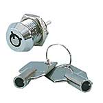
THIS IS THE KOOLEST PART OF THIS PROJECT THE IGNITION LOCKING BARREL SWITCH
SKU#106650


Cool, an old style PC 'keyboard lock' switch, my very first CDI keylock used one from an old PC case.
At $5 a pop worth it, just wire it in parallel with the kill button (blue/black) to prevent starting and not in series with the blue wire so current is not an issue which I did on my last design but using a much more expensive switch as it was much harder to defeat with a 4 tumbler cash register key switch.

This is great, we are all sharing idea's and designs to make improvements ;-}
 

ivan H

Member
Oct 8, 2011
622
1
16
australia
Hi, it is really great, this shareing ideas & the CDI is evolving into something that is superior to anything else available. Thanks for posting the Digikey part No.s Huffydavidson. I'm looking forward to KCVale's circuit board design (& will be using), so I regret wot I have to say next. I know I said the values u proposed would do it perfectly, but after a think I realized that "should" the teimpot's wiper loose contact, the resistance value would go to 19 + ohms which would really over advance the timing. With the 16 ohm normally used & 220 & 120 ohm being put in parallel with, should a jumper vibrate off, the timing can only go to the most advanced setting normally offered, which is still quite safe. We need that in the event of a trimpot failure, the resistance does not go much above 16 or almost 17 ohms maximum, preferably around 16ohms. Cheers
 
Last edited: