LEDs and the infamous White Wire (Questions)

GoldenMotor.com

Shlink

New Member
Oct 3, 2010
23
0
0
USA
I've been reading countless threads about lighting solutions since before I even bought my motor. Now I'm 90% done with my bike and still have not decided on a system. If possible, I am going to avoid batteries.
Its my understanding that the white wire puts out 6 volts, and you do not want to draw more than 3 watts/0.5 amps.

I've been looking at the stats on some LEDs from superbrightleds.com and have been using their Resistance Calcualtor.
These are the LEDs I'm looking to get (and here is the whole list)
The chart says this LED has a Power Dissipation of 120 mW (Thats 0.12 watts, correct?)
Continuous Forward Current of 30 mA (aka 0.03 Amps?)
and a Forward Voltage of 3.4V

It also shows "Peak Forward Current (1/10th duty cycle, 0.1ms pulse width)" at 70mA. I'm not sure exactly what that means and I'm for the most part ignoring it for now.
And under Forward Voltage it says MAX is 4.0v. Does that mean the LED WILL burn out past 4v?

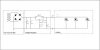
OK Onto the resistance calculator.. assuming I supply 6 volts I'll need roughly a 100 ohm resistor, which will dissipate 88mW in the LED and 68mW in the resistor. Do I just add these together for total wattage useage? If I do it would be 0.168 Watts.


Would I be able to hook up like 15 of these without worrying about drawing too much power?
If they pull 0.03 amps each, 15 would be 0.45, which is under the 0.5 amp limit.
And either 0.12 or 0.168 watts would be 1.8/2.52 watts.. still under 3 watts...
Not saying I would actually use 15 of them, but I'd like to know if these numbers are correct.


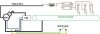
At High RPMs I've heard the white wire can easily supply 10 volts or higher.. so when I put 10v in the calculator it wants me to use a 220 ohm resistor. If I use 100 instead of 220 ohm resistors will I burn out my LEDs at higher RPMs? I guess thats where a battery can come in handy to limit the voltage.

I've got more questions but they rely on whether or not all of the above is true, and this post is starting to get pretty big, so I'll save them for later on.
Thanks for your patience and hopefully someone can help me out!
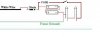
I bet Scotchmo will probably just convince me to use a 1/2 wave rectifier to charge a 6v battery if he reads this :p


TheE

New Member
Jun 26, 2009
185
0
0
Canada
Uhh, let's see what I can answer:

The "peak forward current" business means you can overdrive the LED by that amount for a short period of time without burning it out. Kind of like when you run a Chinese 2-stroke at full throttle...

The forward voltage is the voltage drop across the LED when it's fully on. This doesn't mean the LED will burn past 4V, because anything after 4V will appear across your resistor. This is how the resistor value is calculated, btw.

One thing that is interesting is the max reverse voltage which is rated at 5V- don't use the LED as a rectifier on the 6V system!

And yeah, the resistor has to be chosen for the highest voltage possible, this is a shortcoming of using a resistor to limit the current, unfortunately =/


Hope that helps some...
 

Shlink

New Member
Oct 3, 2010
23
0
0
USA
Thanks TheE that helps. As long as i hook up the anode to the white wire then i'm not using the LED as a rectifier right?

I'm still curious if these are drawing such little power that I could use 10-15 of them without there being any problems
 

TheE

New Member
Jun 26, 2009
185
0
0
Canada
No, you need to put a regular diode in series with everything, following the same direction as the LEDs. Which way you put everything depends which half cycle of the magneto you want to use. Naturally, you want to aim for the one that the CDI doesn't work off of.

Imho, the best way to see how many LEDs you can hook up would be to just keep tying on resistor-LED combos in parallel until the voltage starts to sink. If you want to go the calculation route, the easiest way is to multiply the current through a branch by the total voltage: 6V*30ma=0.18W each (this will increase as voltage increases).
 

Scotchmo

New Member
Jun 23, 2009
217
0
0
Los Osos, California
You said that you are going to use multiple LEDs. Instead of using resistors, you could try pairs of LEDs in series. Two LED’s in series should work ok on about 6 volts.

The white wire voltage fluctuates with rpm. It is not 6v but that is what we call it since at sufficient rpm, it can charge a 6v battery. It might be 3v at low rpm or 7v at higher rpm. If you do not want to use a battery to limit the voltage fluctuations, you could use a zener diode to at least prevent the high voltages that might burn out the LEDs. The zener clamps the voltage at a set limit.

If I were trying to use LEDs with no battery and I wanted consistent brightness, I would use a 3.3v, 5w zener diode running from white wire to ground. Now your white wire can only deliver 3.3 volts and it will do it throughout most of the rpm range. And you do not need to add resistors to the LEDs.
 

Shlink

New Member
Oct 3, 2010
23
0
0
USA
If I were trying to use LEDs with no battery and I wanted consistent brightness, I would use a 3.3v, 5w zener diode running from white wire to ground. Now your white wire can only deliver 3.3 volts and it will do it throughout most of the rpm range. And you do not need to add resistors to the LEDs.
Wow sweet, that sounds perfect. Would using a zener diode limit the number of LEDs I could use? or as long as I stay under the 5w I'll be fine?

Did a quick search online.. does this look like it will do what I need:
http://www.westfloridacomponents.com/DI326PD/1N5333B+5W+3.3V+Silicon+Zener+Diode+Surmetic+40.html
I found a few other websites offering zener diodes for sale with a minimum quantity of 4000 lol.
 
Last edited:

Scotchmo

New Member
Jun 23, 2009
217
0
0
Los Osos, California
Wow sweet, that sounds perfect. Would using a zener diode limit the number of LEDs I could use? or as long as I stay under the 5w I'll be fine?
First of all, 5W is way optimistic. You really want to pull only from the ½ cycle that does not affect the ignition. That is why some earlier posts recommended using a rectifier diode as the first item connected to the white wire (before the zener or else the zener may rob power from the ignition). So you are looking at 2 or 3 watts from the ½ cycle. A 3.3v zener bleeds off the excess above 3.3v. So you are bleeding off about half the maximum power through the zener. That leaves you with about 1 or 2 watts of usable power. That is another reason to use a battery that is trickle charged by the white wire. Then you can use high power lights for periods of time and the white wire recharges the battery when you are not using the lights.

Using the zener can waste some wattage or using resistors on the LEDs will waste about the same. Putting pairs of LEDs in series wastes the least power but they may not light at very low rpm since there is nothing to keep the voltage from going too low or too high.
 

Shlink

New Member
Oct 3, 2010
23
0
0
USA
Ok. Thanks for all of your info Scotchmo. I'll just have to wait until I get my bike running and do lots of experiments. One of the reasons I didn't want a battery is I'm going to be riding a lot during the night (which is also the reason I need decent lights). I don't want to rely on a battery that drains faster than it charges while my lights are on.
 

Scotchmo

New Member
Jun 23, 2009
217
0
0
Los Osos, California
Ok. Thanks for all of your info Scotchmo. I'll just have to wait until I get my bike running and do lots of experiments. One of the reasons I didn't want a battery is I'm going to be riding a lot during the night (which is also the reason I need decent lights). I don't want to rely on a battery that drains faster than it charges while my lights are on.
1) decent lights
2) no battery
3) white wire

pick any two of the above
 

Shlink

New Member
Oct 3, 2010
23
0
0
USA
1) decent lights
2) no battery
3) white wire

pick any two of the above
Hahahaha. Well for now I'm going to experiment with 2 and 3. But I should probably just let go and buy some batteries.
I read in another thread you like to use lithium batteries since they don't get ruined if they are fully discharged. After searching I could only find cell phone and camera batteries. Do you know where could I get my hands on a rechargeable 6v lithium battery and roughly how much one would cost?

EDIT:
Ok so it looks like I'll want to use two rechargeable 3v LiFePO4 cells in series.
Is this how everything should look pretending they are 6v LEDs?


But back in reality they are actually 3.4v LEDs;
It probably wouldn't make sense to use the Zener diode anymore since I'm using the batteries to limit my power. So my options are wire them in pairs or waste some milliwatts using resistors.

OR, come to think of it... Why don't I just wire the batteries in parallel since I'm only looking for around 3 volts any way?
Would that cause any problems because of the 6+ volts coming off the white wire?
 
Last edited:

Scotchmo

New Member
Jun 23, 2009
217
0
0
Los Osos, California
Hahahaha. Well for now I'm going to experiment with 2 and 3. But I should probably just let go and buy some batteries.
I read in another thread you like to use lithium batteries since they don't get ruined if they are fully discharged. After searching I could only find cell phone and camera batteries. Do you know where could I get my hands on a rechargeable 6v lithium battery and roughly how much one would cost?

EDIT:
Ok so it looks like I'll want to use two rechargeable 3v LiFePO4 cells in series.
Is this how everything should look pretending they are 6v LEDs?


But back in reality they are actually 3.4v LEDs;
It probably wouldn't make sense to use the Zener diode anymore since I'm using the batteries to limit my power. So my options are wire them in pairs or waste some milliwatts using resistors.

OR, come to think of it... Why don't I just wire the batteries in parallel since I'm only looking for around 3 volts any way?
Would that cause any problems because of the 6+ volts coming off the white wire?
You could try wiring the batteries in parallel (or just use a single battery) but the average charge voltage may be a little too high. But since the white wire coil has a high resistance and produces such a low current, you may be ok. If it worked, that would actually be a perfect voltage for LED lights. And it would make for a simple system. Try it but monitor your battery voltage at first make sure that you don’t ruin the battery. I prefer a 6v system since there are off the shelf 6v components such as turn signal flashers and horns that operate on 6v.

You show a positive ground system in your diagram. I’m not sure about the coil on your particular HT but I use a negative ground system. A positive ground system robs power from my CDI and can kill the engine.

Putting pairs of LEDs in series would make them about 6v. I have not actually tried it. If you do a 6v battery/charging system, it would look more like the following (I included a pair of LEDs as the 6v light).
 

Attachments

Last edited:

Shlink

New Member
Oct 3, 2010
23
0
0
USA
You could try wiring the batteries in parallel (or just use a single battery) but the average charge voltage may be a little too high. But since the white wire coil has a high resistance and produces such a low current, you may be ok. If it worked, that would actually be a perfect voltage for LED lights. And it would make for a simple system. Try it but monitor your battery voltage at first make sure that you don’t ruin the battery. I prefer a 6v system since there are off the shelf 6v components such as turn signal flashers and horns that operate on 6v.

You show a positive ground system in your diagram. I’m not sure about the coil on your particular HT but I use a negative ground system. A positive ground system robs power from my CDI and can kill the engine.

Putting pairs of LEDs in series would make them about 6v. I have not actually tried it. If you do a 6v battery/charging system, it would look more like the following (I included a pair of LEDs as the 6v light).
Hm. In my Diagram the black wire coming out of the motor would also be attached to the frame, is that still a positive ground system? I added the motor and CDI to the pic. I thought a positive ground system was where you hooked the + side of a battery to the frame so it was always hot. I'm just trying to use it to end the circuit of my LEDs

I'm confused about your diagram. It seems like the high RPM 12+ volts would still be getting to my LEDs (unless the fuse burns out)
 

Attachments

Last edited:

Scotchmo

New Member
Jun 23, 2009
217
0
0
Los Osos, California
Hm. In my Diagram the black wire coming out of the motor would also be attached to the frame, is that still a positive ground system? I added the motor and CDI to the pic. I thought a positive ground system was where you hooked the + side of a battery to the frame so it was always hot. I'm just trying to use it to end the circuit of my LEDs
The black wire attached to the frame is a ground. The coil is also grounded internally. Whether it is positive or negative ground depends on the direction of your rectifier diode and which pole of the battery is grounded.

I don’t know what your diagram is trying to do. You have not grounded either pole of the battery. The battery, the charging circuit, and the lights, should all be parallel circuits. You have all three in series. You are positively grounding the batteries through the LEDs. You don’t show the direction of the diode. You have no switch to shut off your lights.

Try adding a light switch into your diagram and then it may be more obvious why it is wrong.

I'm confused about your diagram. It seems like the high RPM 12+ volts would still be getting to my LEDs (unless the fuse burns out)
In my circuit, the lights are parallel with the battery so they only see the battery terminal voltage of 6v. The battery absorbs any excess voltage put out by the white wire at higher rpms. The only way for the lights to see 12v in my circuit is if the battery terminal voltage were 12v. It won’t happen with the feeble output of the white wire. I originally used a zener diode to protect the battery from over voltage charge conditions, but found that it is not needed with the white wire, as even a 1ah battery can absorb all the output of the white wire.
 

fssntuff

New Member
Nov 12, 2010
6
0
0
Tucson, AZ
A quick question in the middle of this. I have a GT5, is it positive or negative ground? Can't find VOM to check, and when jury rigging a quick test engine dies with anything hooked up to white lead from magneto assuming a negative ground.
 

Scotchmo

New Member
Jun 23, 2009
217
0
0
Los Osos, California
A quick question in the middle of this. I have a GT5, is it positive or negative ground? Can't find VOM to check, and when jury rigging a quick test engine dies with anything hooked up to white lead from magneto assuming a negative ground.
This is how you check to see if a positive or negative ground should be used:

Hook a diode to the white wire. Ground the other end of the diode while the motor is running. If the motor dies, reverse the diode and try it again. The motor should keep running.

Striped end of diode hooked to white wire equals a positive ground, other way is negative ground. Let me know how yours ends up.
 

fssntuff

New Member
Nov 12, 2010
6
0
0
Tucson, AZ
@Scotchmo,

Okay makes sense, as I hook up the system of LEDs, positive side to the white wire and negative to ground and it died, it looks like positive ground then. Will retry tomorrow when there is light again.

My thoughts were to take a couple Lithium cell phone batteries, wire them up in parallel and use them with lighting. The batteries are 3.7 Volts and 1400mah so should work fine for lighting, and the voltage from magneto should keep them topped off during day. It ahold generate enough power for lights. If I can work it out, might be able to make up a turn signal and brake lights as well. Will see if it it positive ground and go from there.
 

Scotchmo

New Member
Jun 23, 2009
217
0
0
Los Osos, California
@Scotchmo,

Okay makes sense, as I hook up the system of LEDs, positive side to the white wire and negative to ground and it died, it looks like positive ground then. Will retry tomorrow when there is light again.

My thoughts were to take a couple Lithium cell phone batteries, wire them up in parallel and use them with lighting. The batteries are 3.7 Volts and 1400mah so should work fine for lighting, and the voltage from magneto should keep them topped off during day. It ahold generate enough power for lights. If I can work it out, might be able to make up a turn signal and brake lights as well. Will see if it it positive ground and go from there.
Use a single rectifier diode for the test, not an LED.

You may be able to set up a 3.7v system as you proposed. The voltage seems a little low for a white wire system but it may charge even better than a 6v system. I use two lithium batteries in series and it works well with the white wire and 6v lights.
 

silverbear

The Boy Who Never Grew Up
Jul 9, 2009
8,325
670
113
northeastern Minnesota
Excuse me for taking this slightly off topic, but do any of you know which wire on a 4 stroke HS or HF engine is the equivalent of the 2 stroke whjite wire? And are they 6v. systems? I'm hoping to e able to do the same on these engines as on the China girl. Many thanks. Good and useful thread...
SB
 

fssntuff

New Member
Nov 12, 2010
6
0
0
Tucson, AZ
@Scotchmo,

Hooking up a 1N4007 series rectifier cathode to ground, and engine keeps running. Hooking up lights after it (a prebuilt to test with), and lights work at 50% duty cycle. If I add a battery pack into the system, I get 100% cycle on the lights. Will draw up a schematic when I get on my desktop later.

Thoughts on lighting are this. If I go to 3.6/3.7 volt system for lights, it means I will be able to use the three cell lights that are re-wired/nodded to be driven off magneto/battery pack combo. I am curious, will have to wait till next pay day to replace meter and Check voltage output, but think this will give battery a charge half the time, and power lights. Might have to add voltage limiter to keep it from going to high, but easy. Lower voltage LEDs will mean less power draw, which should allow more lights to be powered off system.

Thoughts on this one?
 

fssntuff

New Member
Nov 12, 2010
6
0
0
Tucson, AZ
@Scotchmo,

This is what I have come up with so far. I put in a full wave rectifier and voltage regulator. I should be able to use any LED or prepackaged lights that use two to three standard 1.5 volt batteries for power.
 

Attachments