

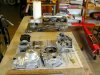
This thing just gets stranger. Found 2 broken trans gears in the engine, guess thats how I got it for free. Tore it down and after a bit of looking and rearranging of the gears now have a 1 speed. To start it, press the shifter down to neutral, after its running shift up for drive. The inital overall ratio is 16:1, maybe a bit low, but I have an adjustable primary pulley that can quickly change that. Got real familar with the insides of the Honda clone engine, its pretty neat.
Latest Lunacy--Honda CT70 Clone Build
- Thread starter cannonball2
- Start date

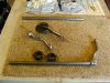
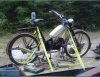
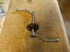
Finally getting in a few parts. Found a good deal on 16" 5/8 keyed shafts on ebay @ $10.95. Bought two to have one in stock as one will make the pedal and jackshaft for this build. Got the locking collars to use to mount the jackshaft assb. to the bike. The only way I do it now. Waiting on the engine parts now. Bought a new 49cc 3sp auto Lifan to have on hand just in case the 48/70cc doesnt work out like I planned. Got the pedal shaft under way. The small front chain ring is ready to weld, then time to cut and finish the shaft. A couple of pics of the slow progress. Engine in pieces etc. Laying in the back in the center of the first pic is the "magic" pulley that will make this a belt primary.
Attachments
-
 133.3 KB Views: 176
 -
 138.6 KB Views: 205
Those split collars I just found out about recently and they are great as they do not scratch up the jackshaft with set screw as the kind that set screw goes direct on to the shaft.
In some cases I found that a pulley is already in just the right position to eliminate the need for the collar as it act as one while also being used for its original purpose, the pulley.
http://www.use-enco.com/CGI/INSRIT?PMAKA=990-3537
5/8 ID,1 5/16 OD,7/16W CLIMAX 1PC CLAMP COLLAR
http://motorbicycling.com/showthread.php?p=393202#post393202 see post #47
You are right on using the split collars on the jackshaft not marring the shaft. The set on the standard lock makes removing the shaft a pain until it is filed smooth. However thats not what I am using these collars for, they are mounts. See the first pic in the link. These have worked out so well its how I mount the major components now. The engine on this build is mounted the same way.http://motorbicycling.com/showpost.php?p=382814&postcount=13
I don't know how I missed this thread. It's a good one. So many things to comment on, but one for sure is to second your vote on the k-10 fork. What a great, solid fork that is, absolutely smoothing out the ride.
The first build came out very nicely, an under the radar light motorcycle...now I'm watching this second one.
SB
The first build came out very nicely, an under the radar light motorcycle...now I'm watching this second one.
SB
CB, I did see how you used the collars that must be the two part type from:
Re: 1900s Vintage Style Build Page 13
In the picture I see the nice weld to two of these clamps that hold the pillow bearings in their holder for the short jack shaft. They go on the frame seat post tube near the bottom.
I have these seat post clamps I got for cheap that are OK that I can spread the steel enough and put them in the same place as you did in the picture. Only that you can’t do that with the cast single split collar, but the type that are two parts and have two set screws to assemble, that is probably what you have. Nice! To make adjustment up and down or removal is quite simplified with this construction.
From the posted link above in #64 the jackshaft has a pulley that is on that same jackshaft as the sprocket. It seems that an idler 3rd pulley tensions up the belt, or is used as a manual clutch like the old style motorcycle stuff with a clutch without any wet or dry pressure plates attached to the engine.
I see that the center space between the pillow bearings have nothing on the jack shaft which I understand is just necessary for a firm mounting for the jack shaft.
The chain on the sprocket and the belt on the pulley are on one side and the other side the jack shaft does not protrude and only goes far enough into a pillow bearing making a good set up. I would think that a sideways force right to left, which there does not seem that there would be any, could have the jackshaft not stay in the pillow bearing on the right as there are no collars on the jack shaft anywhere.
The sprocket on the jack shaft, if it is directly up against the left side pillow bearing would not allow the shaft to go sideways to the right, but not visa versa. At least one collar on the right side of that pillow bearing or the pillow bearing on the right if the jackshaft protruded enough, would set it not to move left or right.
How are any possible sideways forces not to affect the jackshaft?
Just normal running the belt and chain would I suspect have it eventually creep sideways and the whole thing come apart, which I am not thinking you have happening, but how do I get this wrong? What keeps if from moving sideways?
MT
Last edited:
Sorry guys I didnt mention the first pic was in the mock up stage. I was using a short left over piece of shaft. The second pic in the link shows the finished jackshaft, you can see it uses a one piece lock collar. The bike in this build will essentially be set up the same, will just use the engines auto clutch instead of the idler style clutch on the Vintage bike.http://motorbicycling.com/showpost.php?p=389145&postcount=66
SB, I really like the K10 front end, I have another, but dont know if it will wind up on this bike.
SB, I really like the K10 front end, I have another, but dont know if it will wind up on this bike.
In reference to the 125cc build, why do you need a jackshaft, is it just for alingment purposes? Couldn't you get the right gearing through the engine sprocket and the driven sprocket on the rear axle? I don't understand the need for it. I'm sure there is one or you wouldn't be doing it.
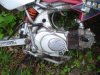
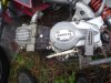
Staring at that engine should looked familiar and I realized that an engine I picked up is almost exactly like it with some different markings, but same shape, 125cc, kick start, gears. It had been on a dirt bike with direct drive from engine sprocket to rear axle sprocket. Mine is also 17" long. Which of course got me thinking fast thoughts...
... and also reminded me of a build I have sitting way out on a back burner which I started last summer. I believe you commented on the thread at the time. It is an old AMF Roadmaster frame with K10 fork and a 2 speed Tomos engine (also 17" long) hung under the belly. I have another one of those frames, too, and also another K10 fork. I just checked that 125cc engine and it urns over with the kick start, so is not frozen up. Carb and exhaust are missing. Looks like someone was "fixing it", got in over their heads or lost interest and it ended up at the landfill, briefly as I brought it home with me to steal parts from.
So that's why I'm curious about the need for a jackshaft. I don't know that I would do this as a build or not, but I have most of the stuff sitting around already and yours sounds like a killer ride. I'd cut the engine mounts off of the dirt bike and reuse them. Maybe off in the future a year or two away.
SB
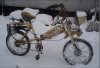
Here are photos of that AMF/Tomos. Frame might need to be stretched a bit.
SB
SB
Attachments
-
 102.2 KB Views: 208
 -
 135.7 KB Views: 204
 -
 132.2 KB Views: 204
SB, to keep the engine centered the jackshaft was necessary. I wasnt happy with where the engine was if directly driven. I believe there have been other clone engined bikes that were driven directly, just wouldnt work for me with this frame. Was originally to be driven on the left side, but had a much better chain line on the right. Was kind of a quirky build but yielded a nice bike. These are wonderful little engines. Was very impressed with the internals of the one I am repairing. You should build one if you have the parts. The stuff you are missing is not very $$. I saw a new carb on ebay for $20. It takes a minimum of a 3" stretch or more depending on the frame to keep the engine out of the front wheel, but the K10 fork almost makes it work as it kicks the wheel forward with the tripple tree. Best to keep the engine as low as possible@ 45lbs. If low the weight actually makes an excellent handling bike.
The AMF/Tomos build is cool! If yo look carefully at the front wheel on the 125cc bike you will see it is extended past the original axle line. Maybe a similar set up would get you the distance you need with the Tomos. Was easy to do.
The AMF/Tomos build is cool! If yo look carefully at the front wheel on the 125cc bike you will see it is extended past the original axle line. Maybe a similar set up would get you the distance you need with the Tomos. Was easy to do.
The Tomos is OK for wheel clearance as I intend to run either 24" or moped wheels or about the same diameter. I made horizontal dropouts for it this winter which gives more clearance in back. Your build is inspiring me to get this AMF/Tomos on the road to see how it handles.SB, to keep the engine centered the jackshaft was necessary. I wasnt happy with where the engine was if directly driven. I believe there have been other clone engined bikes that were driven directly, just wouldnt work for me with this frame. Was originally to be driven on the left side, but had a much better chain line on the right. Was kind of a quirky build but yielded a nice bike. These are wonderful little engines. Was very impressed with the internals of the one I am repairing. You should build one if you have the parts. The stuff you are missing is not very $$. I saw a new carb on ebay for $20. It takes a minimum of a 3" stretch or more depending on the frame to keep the engine out of the front wheel, but the K10 fork almost makes it work as it kicks the wheel forward with the tripple tree. Best to keep the engine as low as possible@ 45lbs. If low the weight actually makes an excellent handling bike.
The AMF/Tomos build is cool! If yo look carefully at the front wheel on the 125cc bike you will see it is extended past the original axle line. Maybe a similar set up would get you the distance you need with the Tomos. Was easy to do.
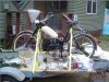
I took a couple pictures just now of the 125 cc 4 speed. See what you think it is. Looks similar, but not quite the same. I think it would fit under the other AMF frame about the same since both engines are the same length. It looks to me like the engine sticks out a bit more on the right than on the left, so it is not perfectly centered, but also not bad. I don't see how it would be possible to have pedals unless the frame was stretched a good bit to leave room for a pedal chain ring. On the other hand, extending the frame is possible. Sometime this summer I'll pull the engine and do a little more research on it. Don't mean to be diverting your thread. As always, your builds provoke thought and inspire.
SB
Attachments
-
 262.2 KB Views: 159
 -
 258.7 KB Views: 154
Must have missed CB2's reply to needing jack shaft on post 71 ... oops
anyway what I wrote:
From: MT
SB, see post 61 above that CB2 mentions about a messed up gearing in the engine that he I suppose salvaged as best as can be without major overhaul and maybe prohibitive cost. It limits to 1 speed at a 16:1 ratio. He goes on to mention that he feels it to be a little low. Also another engine bought and in the wings, he mentions as a possibility that he may use instead and maybe that would not need the jack shaft.
I was expecting maybe wanting more gearing down ratio, but I’m more for dirt bike hill climbing so I guess it can do with less gearing down than 16:1 for a faster bike.
CB2, I understand about pics from in the works. (I have posted pics also where like I have the brake lever 180 degree the other side of the handle bar… just so that it will fit in my truck and fit)
The page 7 of the old beast shows very nice light blue paint and the jack shaft end sticking out partially even after the 1 piece clamp.
I really noticed it was a mock up from the other side also in some pics where close up. I know you would want at least the shaft to be even at the end or a little more, but no less. You surely would not have left about ¼ the distance inside the pulley for enough shaft contact!
Something not quite analogous to this but worth mentioning, rule of thumb is to have when having drilling two holes to have at least half the diameter of the largest hole for separation between the two.
MT
PS Centering by weight rather than volume if necessary by use of jackshaft also a reason for good handling. I though did ride a direct drive with belt, no clutch at all, and the engine hanging off the right side with my leg over the engine... kind of crude ride but was fun back in my teens!
Last edited:
SB the Tomos is way cool talk about it all you want, this is a general purpose thread any way. Thats the Roketa version of the Honda, Its similar but not exactly a clone. They seem to be good engines though. The Lifans and some of the other makes are exact/very close clones. The Roketa should work fine. This bike I am finishing will have pedals, its a tight squeeze though. Thats why it has a jackshaft mounted on the seat tube, to allow the use of the bottom bracket. The chain just BARELY clears the rear engine mount bolt.
MT, seems strange the obsession to center the 125cc when I have several greatly offset FDs, just didnt look right to me. Functionally I doubt it would matter. Probably carve a great right turn.
MT, seems strange the obsession to center the 125cc when I have several greatly offset FDs, just didnt look right to me. Functionally I doubt it would matter. Probably carve a great right turn.
CB2 I had mentioned the centering by weight as I heard from a friend that said that something about handling at speed and I think turning there was some connection.
I definitely agree that looks count so if it does not affect too much a degree go with it.
I also thought wind resistance at speed I suppose could be also a consideration for symmetry. Anyway the friend had one of the newer Indian Motorcycles that since he sold. He got it from another friend that worked for Indian to get them licensed for the use in USA. Part of the deal was he got two of these machines and gave him one. So this friend told me how the Indian Motor Cycle had this as a consideration for weight centering.
My build that is for off roading and did not get much in the way of great looks as I am to be covering it for art mobile and to do riding in the woods. The thing I have too is the vehicle must go slower than 5mph and without the greater gyro affect at speed, the weight with extra skeleton and fabric cover I want it to be stable.
I do want to mention the welding to those small clamps you made such a neat connection without any distortion from the weld. Bravo! I got all the sheet metal almost ready to weld to make a cover over the 10inch pulley that will spin around 500 rpm on one of the dual stack jackshafts so I get a 44:1 ratio and my centrifugal clutch will not heat up by my otherwise need to let it slip by pulse throttling.
MT
Wow, 44:1! That would probably climb a tree. If anybody needs a tow you can probably help em out. I hadnt thought about the loss of gyro effect on bikes at low speeds like you are traveling continously, How are you getting stability?
Thanks for the comp on the welding. I am having trouble seeing(just getting old) to weld like I used to, glasses are a hinderance sometimes as well as a help.
Thanks for the comp on the welding. I am having trouble seeing(just getting old) to weld like I used to, glasses are a hinderance sometimes as well as a help.
The 44:1 I would pull out a pulley of where going between a larger and smaller pulley which are about a 2:1 reduction and replace either of the two so that they match for 1:1. This would effectively halve the 44:1 to 22:1 and that would be my realistic hill climb for the woods off roading bike.
As for welding, I got for my Miller Auto Darkening helmet the optional magnifier lens so that you don't have to wear glasses under the hood. I do however have this low profile gas mask that will fit under the hood while I weld.
I wonder if you know beside wire brush and grinding what would take off chrome. Chrome and stainless steel are very bad vapors to breathe. Actually chromium is in stainless steel and it is poisonous to breathe. Gas mask and some good ventilation necessary for welding, but if as I have heard using that pool additive that is acidic can remove zinc of the plated stuff that you have to rid of for a good weld and also minimize the harmful fumes to be lessened.
I know chrome is supposed to be quite inactive so I don’t know if I can do it that way.
I took a stainless steel bowl that I think has chrome on it and also a steel or stainless steel part from a BBQ cover for some nice already shaped pieces I cut and shaped a little. They are for a cover I will weld up as a safety cover. I got some steel sheet metal to fillet the parts so there are no gaps and a slightly thicker smaller sheet metal part that has enough rigidity even without curved surface to make it cover the 500 rpm 10 inch pulley and the centrifugal clutch pulley with belt concealed so no danger of pant leg getting caught up in it.
MT
And after the murtiatic soak does what you want, flush the part for a while with water. Then do a soak in straight household ammonia for about 30 munites, then flush again and prep for paint ect. Beware that the chromium /acid efleuent is very toxic, so be careful with it and how you dispose of it..
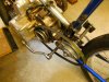
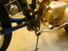
A little more progress. Finished the pedal crank assembly, except for welding the chain ring when the lines are established. Thats the biggest chain ring that will fit and its got precious little clearance at that(but enough). The jackshaft is finished will be adjusted as necessary when its chain line is found and will probably weld the top clamp to permanatly hold the position. There will be a belt idler from the lower motor mount bolt to tension the belt. The pedals will be fully functional, but the ratio will be real LOW. Mainly there for foot rests, and brake applicarion(coaster). The bike will have basic brakes(3), a coaster and side pulls on the rear on the rear and Vs on the front. Should stop pretty well for its speed range. These type engines have super engine braking, which were I ride is about all you need most of the time with a little brake thrown in at the end. BTW this set up is in the same basic ratio range as the 4G Grubee with the 80T sprocket(the 4G is in the 17s I believe, this one high 16s). I have a 4G and it is a good powerful single speed set up. This is actually a 70cc even though it says 48cc(how lucky can you get!) so it has around 5.5 hp should, make a bike with good power, plus its a kick start and can run lights later If I want. Bike is in the mock up with a junk engine and pretty ugly, kindly overlook this.
Attachments
-
 134.6 KB Views: 194
 -
 122.3 KB Views: 239
 -
 94.4 KB Views: 231