99cc rack mount 3 speed spoke drive MTB

GoldenMotor.com

silverbear

The Boy Who Never Grew Up
Jul 9, 2009
8,325
670
113
northeastern Minnesota
That is a really good deal on that engine Silverbear, clone engines cost a whole lot more than that here unfortunately.
The eternal question, 'Do I need another bike?' Possibly not, but the question really should be, 'Do I need the pleasure building another bike will give me?' The answer to that question is easy, - 'Yes!'
Other than reading books, building these bikes and in fair weather riding them is my entertainment. I don't smoke, drink other than an occasional beer and I'm too old to care about girlfriends. Library is free and these bikes are my indulgence. I've also met and made friends with some pretty terrific people here, so it really has nothing to do with whether or not I need another bike. But as you suggest, I do need the pleasure, challenge and camaraderie of putting them together with friends.
Sb
 

silverbear

The Boy Who Never Grew Up
Jul 9, 2009
8,325
670
113
northeastern Minnesota
CB2,
I'm sorting through my stuff, setting aside components for the jackshaft which I'll be making up this week once the 79cc Predator arrives and I see where it will sit on the rails. The jackshaft will sit forward of the engine toward the seat post. I've been looking at the seat post roller drive mount you have for the Maytag build and am beginning to think through the one I need to make up.

The engine mount and jack shaft rails can be rigid as I see it. A rod at the back end of each rail will go down to the rear wheel dropout area and bolted. I don't see any reason now to make the height adjustable since the roller drive will mount at the seat post. And since I am running a centrifugal clutch off the engine crankshaft, I don't see any need for the drive roller to hinge... just be slotted so it can be adjusted against the tire.
I'm guessing that a spring loaded idler pulley would be a good idea between the engine and jackshaft, what about one between the jackshaft and roller drive?

Or am I seeing this wrong? If there's a better way I'm all for what is best.
SB
 
Last edited:

cannonball2

Well-Known Member
Oct 28, 2010
3,682
221
63
Colonial Coast USA.
Your idea sounds like a good approach. I agree that the entire rail mount can be rigid. Im not sure how you are mounting the JS bearings but most pillow blocks have a bit of adjustment. If you are able to size the belt very close you may be able to get away with out an idler. The less the better. In fact I have a belt calc that is pretty accurate. You may want to set the engine/JS locations around belt size rather than just random and then finding the belt.

A seat post hub mount can be swung off the post with at a single pivot with a thru bolt. If you feel the post is too thin to support the bolt add a second seat tube. I have done this many times. It will not be too difficult to add a threaded tension rod to the post mount to apply the hub loading. Try to locate the hub as far down the post as feasible to have a good belt run once again locating by belt calculation. The hubs swing may tension the belt also, but its difficult to get tension and loading to come together at the same time so a spring idler maybe the easiest route on the hubs belt. You can also run a rigid hub mount with slots as you propose and if using the shaft lock collar mounting method the mount will move on the post for tension. This method would be the best.
 

silverbear

The Boy Who Never Grew Up
Jul 9, 2009
8,325
670
113
northeastern Minnesota
CB2,
Thanks for helping me think this through. The pillow blocks do indeed have slots for a bit of adjustment and drilling their mount holes in relation to a standard belt size makes good sense.

I had thought to follow your suggestion about locating the drive roller off the seat post, but after a cup of coffee's worth of staring there isn't enough real estate to do that without locating the mount high up almost on a level with the rails where it is fairly distant from the tire. The junction of frame members and location of the derailleur hardware blocks off everything lower. So I'm back to puzzling out how to mount the drive roller off the tail end of the rails. Once I have the new engine in hand I can see how far forward on the rails it can sit.

About how much belt distance between pulleys is enough?
SB
 
Last edited:

cannonball2

Well-Known Member
Oct 28, 2010
3,682
221
63
Colonial Coast USA.
SB, you might consider ditching the front derailleur and running one of the front sprockets fixed with the rear bring the shifted derailleur. You will still have multi-speeds and the front sprocket can be "shifted" by hand if needed.

This may allow the hub to mount about mid point on the seat post giving a decent position for the hub and an adequate belt run.
There is no specific belt spacing, but a nice even distance makes it easier. Give me the distance between the shafts that seems workable, the pulleys sizes and I will calc. a belt length.
 

silverbear

The Boy Who Never Grew Up
Jul 9, 2009
8,325
670
113
northeastern Minnesota
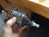
While I'm waiting for the new engine and tires to arrive, this is a good time to step back for some "creative staring" to review options, then assess things again when the new tires are mounted, possibly giving a different profile, and to see how the engine wants to sit on the rails... how far or close in relation to the seat post and how much offset if the engine did a direct drive to the roller hub. If the offset feels like it will make the balance feel weird then the seat post and jackshaft is about the only option, requiring changes to the derailleur system. Also the best spot on the seatpost for a jackshaft is taken up by a frame member union. If the offset is not much then it may be that situating the drive and driven pulleys to the inside of the rail with the horizontal member of the angle iron removed so the belt has clearance may be a viable option. If so then the rail engine and hub mount needs to be adjustable. There are advantages and disadvantages to each approach. We'll see.

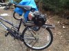
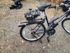
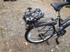
In the mean time I've been cleaning up the 99 Predator, discovered one of four bolts at the base of the engine holding it to the frame mount was missing. Changed the oil in the crankcase, new spark pug, may make a new copper gas filter for it while making a second one for the new 79cc engine. Start fresh with plenty of clean fuel. I also did some paint touch-up, will check over the Q-matic transmission and rear wheel and then reassemble the panther. And to satisfy the dog, re-attach her canoe sidecar.

Spring has finally sprung here in northern Minnesota so both dog and bear need to ride! Should be lots of progress next week and once the bikes are riders I can pretend responsible, adult like behavior and get the 4 cords of maple logs cut & split for winter 2 years from now. Break time from "making wood" (local expression) will be shortish, couple mile rides for man and beast down Bearhead Rd. Woohoo!
SB
 
Last edited:

cannonball2

Well-Known Member
Oct 28, 2010
3,682
221
63
Colonial Coast USA.
Looking at the pics of the bike the hub can be easily mounted at the center or slightly upper portion of the seat post which is a good place, possibly not even interfering with the front derailleur. If using the locking collar mounts one can be placed above and one below the top frame rail with enough spacing between them to allow plenty of adjustment. As the hub is moved down it will load the tire.
I think it best to mount the hub first then build the rest around it, otherwise you are not really sure of dimensions, offsets, etc..
 
Last edited:

silverbear

The Boy Who Never Grew Up
Jul 9, 2009
8,325
670
113
northeastern Minnesota
I know you have a lot more insight into this setup than I have. The consideration of direct drive from engine to hub was partly due to complications at the seat post hub mount. I wasn't planning to use the split lock collars because I'm a crappy welder and had figured on making the mount using a CB antennae mount I had bought at one time for an engine mount, but didn't use because of torque concerns with a five horse motor. For this it would be strong enough, I think. That would be the base of the mount and I had figured the rest could be done by cutting, bending and bolting, but it would not work in this case because of that frame member. With the mount I intended to use it could not straddle that frame member. Split collars with one above and one below would be just right, agreed. I remember Steve having some trouble welding engine mounts to the lock collars two summers ago on the Elgin Velocipede. Something about the coating on the collars if I remember right, but the point is that Steve is a pretty good welder and if he had trouble, my chances of success are slim. So that's why I keep returning to the idea of direct drive.
Thanks for being patient with me. I'm trying to do this within my skill set and budget. I had hoped for something really simple, but that isn't often how things work out.

And I admit knowing nothing about derailleurs gear systems. I think I rode a 10 speed once. So, I hesitate to mess with it and am not really interested enough in how they work to learn. Looks complicated.
SB
 

curtisfox

Well-Known Member
Dec 29, 2008
6,048
3,955
113
minesota
One could maybe mount the jack shaft to the front of the seat post? Can't really tell would need to be there and see it to figure it. Also you could get it all ready and take it to a welder in town and have that spotted and would only coast a couple bucks.

When you get the motor and post some picture and then we can tell better.............Curt
 

silverbear

The Boy Who Never Grew Up
Jul 9, 2009
8,325
670
113
northeastern Minnesota
New tires came today and are now mounted. I cobbled an old copper drop stand made for something else years ago and it is good enough for now. Holds the bike up. Hub has been cleaned and oiled. The oil cap can be used with the spokes in place, so maintaining the hub will not be an issue. I can see how the front derailleur is not needed. Can I just remove the hardware and leave the chain on the sprocket of choice? And then it will be a five speed pedal bike? I guess it would be the big one up front for easier pedaling. Is that all I need to do? Looks simple enough. Tomorrow I'll make up rail supports reaching up from the dropout region and tomorrow evening the 79cc motor should be here. If not, then the following day. Still mulling over the hub mount on the seat post. Removing the gear hardware would free up some real estate.
SB
 

Attachments

cannonball2

Well-Known Member
Oct 28, 2010
3,682
221
63
Colonial Coast USA.
Just remove the derailleur and its associated cable/shifter etc. The smaller the sprocket on the front the easier it will pedal. Start on the middle sprocket. You can always just shift them by hand later it that doesn't suit you.

Consider making a swing mount that pivots from the frames top tube right in front of the seat post. This will make the hub mount very rigid and offer good travel. A threaded rod could run down to the area where the kick stand would be to add the down force. The length of the arms of the hub mount will determine where it contacts the tire. If you make the arms so the mount will be at a slight upward angle then the down force will pull the hub firmly into the tire with no danger of it over riding center(of the tire) and exiting below. This will also give some need room for a secondary belt run form a jack shaft(assuming centered engine) to the hub. To make mounting easier for pillow blocks see if the angles can be flipped over with out interfering with the engine(or trimmed) this may make the mount too wide though.
 
Last edited:

silverbear

The Boy Who Never Grew Up
Jul 9, 2009
8,325
670
113
northeastern Minnesota
I think the swing arm is a very promising idea and will give it thought during the day. Flipping the angle iron rails is also something to consider. I will make up some kind of supports for the rails today so the engine has a place to sit while seeing how things might line up. Thank you once again for giving this your time. Your descriptions of how things might be done is not only helpful to me, but also for anyone else reading along and following the problem solving process in doing a build of this kind. Challenging fun! Engine should arrive today... oh boy.
SB
 

silverbear

The Boy Who Never Grew Up
Jul 9, 2009
8,325
670
113
northeastern Minnesota
I made supports for the rails from aluminum tent poles and cut and bolted a tail piece. Feels solid. I set the 99 engine on the rails to get some sense of placement. I believe the footprint of the 79cc is the same, if not the 99 is close enough to help me visualize. The rail width will allow some off center placement if wanted.

Engine just left S.C. today and is expected here Friday.

Between now and then I'll work on a hub mount.

Curt, I think we should go with the 6" pulley on the hub roller rather than the 7". What do you guys think? I'm still considering the possibility of direct drive from the engine clutch pulley and no jack shaft. There is virtually nothing on the right side of the engine and a good bit on the left, so off center might still be centered as fas as weight. No jackshaft would let the engine sit farther forward. It could tuck under the seat. We'll see.
(cont.)
SB
 

Attachments

Last edited:

silverbear

The Boy Who Never Grew Up
Jul 9, 2009
8,325
670
113
northeastern Minnesota
This is what I would like to use for the base of the hub mount. It is a slightly modified cb radio antennae mount. I will attach a roughly U shaped piece of steel bent to shape so the center portion can be bolted to the cb mount and the two "arms" will be slotted to hold the 3 speed roller hub. This will not be a swing arm setup, but is adjustable as it can slide up and down the upper portion of the seat post. And the slots in the arms will be deep enough that the hub can slide closer to or further away from the tire.l It might not be ideal, but it will be secure. I think it will work. That will be tomorrow's project.
SB
 

Attachments

cannonball2

Well-Known Member
Oct 28, 2010
3,682
221
63
Colonial Coast USA.
SB, off the top of my head the offset is the biggest hurtle I see. If you mounted the hub to the seat post in some fashion to align with the tire properly could you weld two center less pulleys together to achieve direct drive? If so then you could probably run the engine mostly forward. I don't know if installing or removing the C ring on the inner pulley will be possible for hub service. Keep it well oiled and it probably wouldn't need any.
 

silverbear

The Boy Who Never Grew Up
Jul 9, 2009
8,325
670
113
northeastern Minnesota
I don't understand why two pulleys welded together is necessary... to make it stick out further to the side? To avoid interference from the bike frame? Is that it? Must be. If the center of the outer pulley was opened up wider then access to the C ring might be better. Weld the pulleys together at the outer edge.
SB