HT Bicycle Engine Generator Characteristics

GoldenMotor.com

LEDHead

New Member
Sep 6, 2009
11
0
0
Woodinville, WA
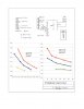
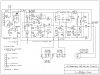
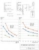
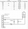
I have read all the threads that I could find regarding the HT engine generator and the possibilities of using the White Wire to power a self contained lighting system. There still seems to be a lot of confusion regarding output voltage and available power. I have done a lot of experimenting and would like to share my findings with the community. The configuration I am using is a fullwave bridge rectifier connected between the WW tap and the grounded end of the coil. I unsoldered the grounded end from the laminate and made a binding post using a 1/2 watt resistor epoxied into the hole in the core adjacent to soldered attach point. I clipped the lead off one side and left 1/8" on the exposed end of the resistor to wrap and solder the fine copper wire of the coil. The '-' pin of the bridge is grounded to the engine case and "+" pin is the output. A schematic of the test circuit is shown in the attached jpg. I used several resistors to load the output and measured the load voltage over 3 engine speeds. The lowest was a putt-putt idle, then a faster idle, and finally rev'd to the equivalent of about 15 mph. The chart on the left shows load voltage on the x axis and load current in amps on the y axis for the 3 engine speeds. The chart on the right is the power out curves for the 3 speeds. The x axis is load resistance and the y axis is the load power in watts. What may be surprising to some is the usable voltage is in the 20V range and around 4 watts can be extracted at reduced voltage. The tradeoff is you have to reduce the load at idle or the CDI will be starved and the engine will die. This is my first post and I am not sure if the the jpg file is attached..flg.
 

Attachments

Last edited:

Scotchmo

New Member
Jun 23, 2009
217
0
0
Los Osos, California
Re: HT Generator Characteristics

...What may be surprising to some is the usable voltage is in the 20V range and around 4 watts can be extracted at reduced voltage...
Your graph did not show up but from my experience, the maximum power point voltage at average riding speeds is about 6v. That is why we use 6v systems. Electrical power falls off fast above 6v.

...The tradeoff is you have to reduce the load at idle or the CDI will be starved and the engine will die...
That is why you should use a ½ wave rectifier for a charging system. Negative ground ½ wave rectifiers do not affect the CDI.

There may be a lot of confusing information but what works is simple. ½ wave, negative ground charging system, 6v rechargeable battery. No regulator needed. Expect about 2 watts of charging current.

Besides your lights and accessories, your electrical system is simply a diode, a battery and a switch.
 

LEDHead

New Member
Sep 6, 2009
11
0
0
Woodinville, WA
Re: HT Generator Characteristics

Thanks for your quick response Scotchmo. I have seen a lot of discussions on charging cicuits and SLA batteries. I have not seen much in the way of measured data and that's why I wanted to share this. BTW I have a LED based system on my bike that I will share. I chose to not use a battery because I wanted a system that turns on when I start the engine and turns off when I kill it.
 

LEDHead

New Member
Sep 6, 2009
11
0
0
Woodinville, WA
Re: HT Generator Characteristics

I have attached the schematic for my lighting system. I admit that it is a lot more complicated than what everyone else is doing but it works really well and requires zero maintenance. The thumbnail file size limitation makes it real grainy and I appologize for that. If anyone is interested in a high res version of the schematic maybe someone can tell me how to include it in a posting. The key to this approach is to use a buck regulator to efficiently convert the relatively high output from the generator down to about 3.5V for the head light LED. I modified the feedback circuit to make it a constant current source for the head light. There is also an astable multivibrator to blink the lights during day light rides and a low voltage shut down to lighten the load on the generator when the engine is at idle. I connected the LED's for the tail light and side lights all in series fed by a curent source. The system draws about 3 watts when the lights are constant on (not blinking). The low voltage circuit limits the supply voltage to 17 volts minimum. When the engine is at idle, the generator outputs only about 1 watt without degrading the CDI. The low voltage circuit limits the consumption to 1 watt by causing the lights to flicker at the rpm rate of the engine. A little throttle and the flicker gives way to solid light. The engine speed at 10 mph and above produces 20-24 volts DC at the input. I added a snubber (27V zener + 33 ohm resistor) to clip glitches produced by the ignition circuit which caused the voltage on the big electolytic cap to creep up to 40V when the lights were turned off. This exceeded the voltage rating of the cap and was at the max for the LM 2575 regulator. Oh, and the other thing I added to the generator compartment is a low voltage controlled engine kill circuit.

I have added a higher resolution schematic of my light system.
 

Attachments

Last edited:

Scotchmo

New Member
Jun 23, 2009
217
0
0
Los Osos, California
Re: HT Generator Characteristics

Your system looks very sophisticated. Much more so than even a production moped or scooter. In keeping with the design of the HT engine, I like to keep it simple. The diagram of my system below is simple, reliable, does not flicker and I have lights even when my engine dies. It uses two AA size rechargeable lithium batteries. All lights are LED lights. And it has a 6v electric horn. My battery has never gone dead. My requirements may be different than yours. This is the minimum system that meets all my requirements.
 

Attachments

thatsdax

Member
Feb 22, 2008
868
4
16
www.thatsdax.com
Re: HT Generator Characteristics

Nice Design. You have everything you need for proper rectification, regulation, and smoothing. Full wave
Vout = 2vp/pi and a Zener for regulation, and a cap to smooth the ripple. Max Power before severe degradation of Spark will be around 3.75 watts or so. The problem is in the coil and the way it was designed. The fact that the White wire shares the load with the rest of the coil is what limits or effects spark since it takes away from the coils total output to the CDI. A separate winding is the cure. I have seen where some guy has added a winding to the other side and I believe this is the best way to go I think. another way to go would be to use your circuit and Zener to keep a battery charged up and this battery would then be used at night to run the lights. In this way.. You could really have some super powerful lights and during the day, you could trickle charge the battery. These are just my thoughts. Enjoy the ride..
 

Scotchmo

New Member
Jun 23, 2009
217
0
0
Los Osos, California
Re: HT Generator Characteristics

LEDHead, we got side tracked from the original post about generator characteristics. Can you post a clearer image of your findings with the axis labeled? That information is valuable for determining what type of electrical loads can be used.
 

LEDHead

New Member
Sep 6, 2009
11
0
0
Woodinville, WA
Re: HT Generator Characteristics

Scotchmo - Thanks for the continued interest. Here are the test circuit and charts with labeled axis. I think the resolution is adequate for viewing.
 

Attachments

Scotchmo

New Member
Jun 23, 2009
217
0
0
Los Osos, California
Re: HT Generator Characteristics

Scotchmo - Thanks for the continued interest. Here are the test circuit and charts with labeled axis. I think the resolution is adequate for viewing.
LEDHead,

Very interesting! I would really like to see you do another of the Amps vs. volts charts, at cruising rpms, but chart from 0v to 12v. That is where the maximum power point should be. Use a diode on the white wire to skip the CDI critical half cycle so that you can load the white wire down to 0v (0 ohms) without killing your spark.

Your existing chart only shows as low as 14v while the electrical power output is still climbing fast. I would like to see where the maximum power point of the negative ground half cycle really is. That would be some very useful information.

The negative ground half cycle has fully usable electrical power. I know that some people also steal power from the other half cycle up to the point where it hurts the spark but I prefer to avoid this.

If you hook a diode with the anode end to the white wire, you can run a direct short of the cathode end to ground without affecting the spark. If you reverse the diode, the engine will die.

Maybe use 0, 10, 20, 30, and 40 ohm tests points.
 

LEDHead

New Member
Sep 6, 2009
11
0
0
Woodinville, WA
Re: HT Generator Characteristics

Scotchmo - I ran an experiment today using a single diode as you suggested. The results are attached. I forgot to write down the part number but I used a Radio Shack 3A 400PIV diode. I tried to determine if loading the negative or positive half cycle would affect the CDI but with my engine, shorting either the positive or the negative half cycle to ground through the diode killed the engine. This happened at low as well as at very high idle engine speeds. I am not sure what this means since the common belief is the CDI uses only the positive half cycle. At any rate I attached the results in a jpg file.
 

Attachments

Scotchmo

New Member
Jun 23, 2009
217
0
0
Los Osos, California
Re: HT Generator Characteristics

Scotchmo - I ran an experiment today using a single diode as you suggested. The results are attached. I forgot to write down the part number but I used a Radio Shack 3A 400PIV diode. I tried to determine if loading the negative or positive half cycle would affect the CDI but with my engine, shorting either the positive or the negative half cycle to ground through the diode killed the engine. This happened at low as well as at very high idle engine speeds. I am not sure what this means since the common belief is the CDI uses only the positive half cycle. At any rate I attached the results in a jpg file.
How about the same test with the diode reversed ? And then both tests at a higher rpm. That is useful data. Maximum power appears to be in the 6v-9v range. Interesting that your motor dies regardless of the shorted diode orientation. A negative ground diode short will not kill my engine. It will slow down a little at idle. I assume that is from the 3 watts of additional drag, and not from making the spark any weaker. I suspect that there is more than one CDI configuration on these HT engines. I have not confirmed it but I heard of another that would run with a positive ground short but not a negative ground short.
 

scottmanesis

New Member
Dec 30, 2010
107
0
0
Austin, TX
Re: HT Generator Characteristics

All this talk of diodes and rectifiers etc has me thinking I need to learn English because 98 percent of these posts are completely not understood by me. So I will sit here and ponder simpler things in life, like time travel for instance or perhaps sub particle nano physics.lafflaff
 

scottmanesis

New Member
Dec 30, 2010
107
0
0
Austin, TX
Re: HT Generator Characteristics

Not to sound like an ignoramous (I am sure it would actually beneficial to learn about the electronics side of things) , but I am just looking to put a light on my bike without having a degree in electrical engineering. None of these posts are shedding any light on the situation for me because I have NO CLUE about that stuff.

You can know some of the things some of the time but not all of the things all of the time :)
Please keep me updated when someone comes out with the buy this light and splice this wire into that wire kit....I'm in!
 

AuNaturalTanner

New Member
May 10, 2011
6
0
0
Kona, Hawaii
Re: HT Generator Characteristics

LEDHead is certainly more advance they I, when it comes to electricity. I have been contemplating his issue to have lights run the same as a motorcycles'. My research lead me to the links below. However, as I said, I am electrical challenged. My hopes are that someone like LEDHead could pick-up the ball and run with it. :)

Whizzer Motorbike

Whizzer Motorbike
 

rohmell

Active Member
Jun 2, 2010
1,531
6
38
New York
Re: HT Generator Characteristics

It is very interesting that the CDI can operate with the black wire connected only to the laminate and no path back to the magneto coil.
 

GearNut

Active Member
Aug 19, 2009
5,104
11
38
San Diego, Kaliforgnia
Re: HT Generator Characteristics

One end of the wire coil on the mag is attached to the laminate mag frame when the thing is wound up at the factory. As a matter of fact, that factory connection is known to suffer from a poor "cold" soldered connection, if it is even soldered at all. Some are simply crimped loosely in place. That connection is the most common reason why mag coils fail.
The black wire is added at the factory to provide a convenient way to complete the circuit when the ignition is installed by the end user. If you really wanted to, you could forgo the use of the black wire at the mag and just run the black wire from the CDI box to a bolt on the engine case. The ignition will still work so long as the poor factory coil connection is sound and secure.
 

rohmell

Active Member
Jun 2, 2010
1,531
6
38
New York
Re: HT Generator Characteristics

If you read the 1st post,the OP unsoldered the wire from the coil to the laminate, thereby isolating the laminate from the coil.

EDIT: I didn't look at the schematic close enough. The black wire eturns to the coil thru the bridge.
 
Last edited: