Hello all again. I'd been back just this afternoon getting back and working on my motor bike.
There was a time almost a year ago when I was giving it a lot of attention, but as it goes working on this at an apartment had some problems with just a few folks that had got ticked off and mentioned to the manager about unsightly stuff on the lawn. I resorted to working on it again and it is OK with the manager, but to keep it directly in front of my own apt and or by the side of the street by the curb.
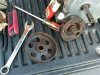
Oh well I had some much stuff that I just got it going back together again and am modifying the drive rear wheel that I made with washing machine pulley and wood sandwich with screws. The mod is to shim the way the tightening screws push on the pulley so that it does not let the force holding the pulley press unevenly. Since it was doing that uneven pressure, the place between the screws along the circumference of the pulley deformed and made a side to side wobble, this would have the v-belt most likely fall off.
I did not have to deal with this problem when I made a couple of motor bikes 35yrs ago. What I was using then were 24 inch wheels. This current one is 26 inch. The 24 inch wheels had less number of spokes. The number of spokes being less then, meant that the sandwich off wood pressing on the spokes would span only 3 spokes each on each of 4 sandwich sets. The spokes did not have much difference in the plane they were in, so the sandwich forces made negligible deformality to the washing machine pulley. The current 26inch wheel, with the wood sandwich spanning across 6 spokes of a plane, that is not even at all and needs fixing. This deforming of the washing machine pulley is just totally unacceptable. I also used 3 wood sandwich sets, which makes it ever more prominent a problem. I could possibly start over with more sandwich pieces like maybe 6. Then I might not need to do this rework of shims. The best I idea that is similar to the Whizzers the way they had the pulley attached to the spokes on the early 1900 designs, that used clips from the pulley to the spokes, that would be something to do. Unfortunately I am not sure how to without expert welding on low temp melt material the pulley is made of to make fasteners to do like the Whizzers were done practically a century ago.
Measure Twice
There is something that I did ready in the more recent previous posts. It had to do with getting a clutch unstuck from the crankshaft of an engine.
Here is what I found. The keyway uses the key to hold not just one groove in the inside of the clutch that slips over the crank shaft and is tightened down with a set screw. There as I found on the clutch that I have, the need to reach inside, look and position the slot on the part that goes to the outer surface of the clutch (the part that has the gears teeth) and also the part that is always spinning when the engine is running. It is the part with the spring and the shoes that get you going after you up the throttle from idle. It too had a keyway slot that has to be in line with the other. It they are both not in line when slipped on to the crankshaft, it usually goes on with a little extra force, but is a bear to remove. If you do see the scratches once hopefully you get the clutch off the crankshaft, I found it best to use fine emery cloth to take the burrs off that were caused by installing improperly by not having both keyway slots lined up before installation onto the crankshaft.
I am not sure why there is a need for two individual slot key way groves for this centrifugal mini bike clutch, but since I recall having the thing get stuck so many times and then find a way to prevent it from happing again, I will always be sure both key way slots are lined up before installing the clutch, then tighten both the set screw. One that goes to press down on the key and the other that just presses on the round of the crankshaft 90 degrees opposed.
Measure Twice
PS anyone know why they are built with two key way slots? I will look on this site and others to find what I can. I'd be interested to know the answer
MY MISTAKE HERE IS THE EXPLANATION:
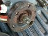
I will attach a picture of the Clutch showing a dimple as for a better term, I don't know, on a sleeve part of the clutch.
It is there as best as I can tell to facilitate the removal and installation of a replacement sleeve when it gets worn out or damaged.
This sleeve is just a way to couple the part attached to the crankshaft of the engine to the clutch drum with the sprocket attached, and that only turns when the engine is above idle.
This is one of the Max Torque Brand Clutch, which model, I don’t know as it is rusty and all I could see is the brand, nothing else. It was from around the 80’s or earlier when I bought stuff used at garage sales and flea markets.
The dimple as I see it is a impression on the outside of the sleeve, that the crankshaft of the engine has to have it’s keyway lined up with to not get stuck. You see the dimple that is a rectangular shape goes into the metal and shows up on the inside of the bore of the sleeve. Then it must be in the keyway groove or else, you are compressing the metal dimple and it scrapes. That is how it can cause the clutch to get stuck on the crankshaft.
The major reason behind having the dimple on the sleeve, as best as I can tell is that it prevents the crankshaft from rotating within the sleeve’s bore, having all that area causing heat from the friction. The end of the sleeve that attaches to the part with the shoes, can rotate at the end, and maybe it is a better place to have it be a bearing surface so it is done that way.
I did not really see a reason why they made it so that a part, this sleeve can rotate independently of the other two moving parts, being the shoes and the drum parts. If it was just how it was designed and not intended but only a way to replace a worn part, then it works for me! It just had me go off on a tangent for a while, till I took the thing apart and that was not so bad. Serendipity has it that it turned out for the best. This is since I had to free up the shoes to move anyway as they were still rusted in place when I got the clutch apart.
The sleeve as I see it could just as well be firmly attached to the part with the shoes and the crankshaft, and not have needed this dimple in it, and then there would be no one wondering how the clutch seems to always get stuck when trying to install and remove. I could get the engraving tool and write on the clutch installation instructions, but at least I know that two items have to line up with the keyway in the engines crankshaft, and that is the clutch key and also this dimple in this sleeve. I just have to grab the inside of the bore of the clutch at the end where the sleeve is with a finger and rotate it till it is in line with the keyway of the clutch. The make sure that the do not move in relation to one another before installing to match on the engines crankshaft keyway.
Measure Twice