EZ MOTORBIKE INSTALLATION
The purpose of this thread is to focus on the installation procedure for the EZ Motorbike. Much has been written about installing two stroke HT engines, but the same is not true for the four strokes. Since more of us are switching to four stroke engines, more documentation is needed. This is my first foray into the world of four strokes, so in that sense I am a newbie venturing into the unknown and this thread is dedicated to those also new to this system and to those wanting to find out what is involved.
The first important step is figuring out what frame is appropriate for the engine. At the EZMotors website there is an ongoing list of appropriate bicycle frames which is being added to as time goes by.. If yours is listed, you’re good to go. If not, do some hard looking and measuring, as a four stroke engine kit takes up more in frame real estate than a little HT two stroke engine.
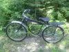
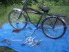
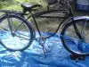
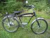
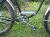
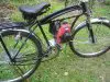
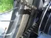
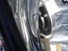
In my own case I picked a vintage Schwinn straight bar frame (panther, hornet, motorbike, etc.) which was a questionable choice. While I love the looks of this classic, it has much less space available than the popular cantilever frame. My feelings are that you want a well made heavy frame, good wheels which preferably have heavy duty spokes and good brakes. Frame and wheels are the foundation of your build. This is going to be a motorbicycle capable of being pedaled, but it is a serious motorbike above all else.
(cont.)
The purpose of this thread is to focus on the installation procedure for the EZ Motorbike. Much has been written about installing two stroke HT engines, but the same is not true for the four strokes. Since more of us are switching to four stroke engines, more documentation is needed. This is my first foray into the world of four strokes, so in that sense I am a newbie venturing into the unknown and this thread is dedicated to those also new to this system and to those wanting to find out what is involved.
The first important step is figuring out what frame is appropriate for the engine. At the EZMotors website there is an ongoing list of appropriate bicycle frames which is being added to as time goes by.. If yours is listed, you’re good to go. If not, do some hard looking and measuring, as a four stroke engine kit takes up more in frame real estate than a little HT two stroke engine.
In my own case I picked a vintage Schwinn straight bar frame (panther, hornet, motorbike, etc.) which was a questionable choice. While I love the looks of this classic, it has much less space available than the popular cantilever frame. My feelings are that you want a well made heavy frame, good wheels which preferably have heavy duty spokes and good brakes. Frame and wheels are the foundation of your build. This is going to be a motorbicycle capable of being pedaled, but it is a serious motorbike above all else.
(cont.)
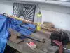
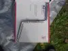
Attachments
-
 282.1 KB Views: 366
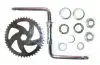
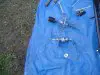
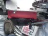
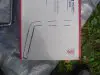
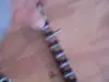
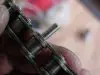
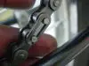
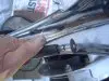
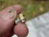
 of mind. It is also a good idea to have a half link as that may be all that is needed to take out too much slack in the chain. While you’re at it, you might want to pick up a half link (#43) for the pedal chain, too. It is worth the extra time getting the chain tension as right as you can from the start.
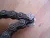
")
")