

Got a picture of how your bridge is set up?I am running a full wave bridge with 3 1 watt led's works fine! bike runs 25 mph uphill with the ligths on. still on the first tank of gas. battery ordered will update soon.
k.i.s.s.---keep it simple stupid.
6 Volt LED headlamp w/ small 6 volt motorcycle battery
- Thread starter SgtNorthcutt
- Start date

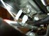
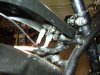
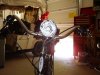
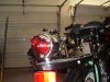
Not the best pics but here they are.
Explaination:run white wire to ac + on bridge run red from dc + I used a battery
powered light that I rewired to accept the dc+ wire for the power instead of the 2 aa batteries
from the switch on the headlight I power the two leds in head light and the 1 in the taillight
$3.39 for the bridge rectifier at radio shack you don't have to use as mnch wire as I did
If you have a similar headlight all connections as well as the bridge could be contained inside the light housing.Maybe I'll do that next time.
K.I.S.S. keep it simple stupid
Attachments
-
 145.1 KB Views: 566
 -
 139.8 KB Views: 555
 -
 141.1 KB Views: 587
 -
 137.4 KB Views: 554
 -
 123.5 KB Views: 475
I’m using a half wave rectifier. The full wave rectifier is normally the better way to go. But on these engines, the full wave gives you a weaker spark which can affect engine performance. Use a half wave rectifier and even a short in your lighting system will not affect the engine.
I have a bicycle 6v headlamp and an automotive 6v taillamp. I have a small 1.3ah lead acid battery. The resting voltage of the battery was 6.30v. I went for a 7 mile ride last night with the lights on in order to run the battery down. Right after the ride, the voltage was 5.89v. I checked the battery this morning and the resting voltage was 6.12v. I went for a 25 mile ride today with the lights turned off. The resting battery voltage was 6.24v right after the ride and settled at 6.20v about 2 hours later. It appears that the charging system is working but the output of the alternator is very small. I’m assuming that it is just a function of the design.
6.30v - initial volts
5.89v - after running lights
6.12v - after 12 hours rest
6.24v - after 25 mile ride
6.20v - after 2 hour rest
I included a zener regulator in my system but after seeing how weak the charging system is, I would guess that it is not needed. Lead acid batteries can stand a limited amount of overcharging better than most other battery chemistries. I will run my system with the regulator for awhile, but I will probably remove it later and test without it.
After this experiment, I would suggest a system using a single rectifier diode to a very small lead acid battery. And the most efficient 6v LED lighting system you can come up with. I'm going to look for an LED bulb for my tail/stop light next.
You don’t even need a wiring diagram. Just hook the diode (Radio Shack part no. 276-1141) up to the white wire. Ground the other end of the diode to the running engine. If the engine dies, reverse the diode. That determines the correct polarity so as not to affect the spark.
For negative ground:
----white wire----[diode I]----[+ battery -]-----ground
For positive ground:
----white wire----[I diode]----[- battery +]-----ground
Hook your lights up to the battery through a switch. You should be good to go.
Diode is about $1, 6v lead acid battery is about $14, switch is about $3, 6v lights can be whatever you come up with.
Last edited:
check out amazon .com for NITEIZE LEDS they have 1 watt and 3 watt
direct replacement flashlight bulbs at the best price I coul find ...about $7.50 ea.
direct replacement flashlight bulbs at the best price I coul find ...about $7.50 ea.
I think that I need to study the alternator/magneto some more. From looking at the apparent connections of the three wires coming from the motor, I don’t see how shorting the white wire would kill the spark but it does. I’m going to study the output of the blue wire to see if I can figure it out.
I also spent a lot of time experimenting with the white wire and must say yours is the best post to ever come along on either of these forums. Should be made a sticky. Personally I prefer to use a cheap LED bike light powered from low discharge NiMH AAs but if there was need for using the magneto power your info would be the place to start.
FYI shorting the white wire draws all power from the blue one because, being wired in parallel, acts like the secondary of a transformer.
FYI shorting the white wire draws all power from the blue one because, being wired in parallel, acts like the secondary of a transformer.
I’m using a half wave rectifier. The full wave rectifier is normally the better way to go. But on these engines, the full wave gives you a weaker spark which can affect engine performance. Use a half wave rectifier and even a short in your lighting system will not affect the engine.
I have a bicycle 6v headlamp and an automotive 6v taillamp. I have a small 1.3ah lead acid battery. The resting voltage of the battery was 6.30v. I went for a 7 mile ride last night with the lights on in order to run the battery down. Right after the ride, the voltage was 5.89v. I checked the battery this morning and the resting voltage was 6.12v. I went for a 25 mile ride today with the lights turned off. The resting battery voltage was 6.24v right after the ride and settled at 6.20v about 2 hours later. It appears that the charging system is working but the output of the alternator is very small. I’m assuming that it is just a function of the design.
6.30v - initial volts
5.89v - after running lights
6.12v - after 12 hours rest
6.24v - after 25 mile ride
6.20v - after 2 hour rest
I included a zener regulator in my system but after seeing how weak the charging system is, I would guess that it is not needed. Lead acid batteries can stand a limited amount of overcharging better than most other battery chemistries. I will run my system with the regulator for awhile, but I will probably remove it later and test without it.
After this experiment, I would suggest a system using a single rectifier diode to a very small lead acid battery. And the most efficient 6v LED lighting system you can come up with. I'm going to look for an LED bulb for my tail/stop light next.
You don’t even need a wiring diagram. Just hook the diode (Radio Shack part no. 276-1141) up to the white wire. Ground the other end of the diode to the running engine. If the engine dies, reverse the diode. That determines the correct polarity so as not to affect the spark.
For negative ground:
----white wire----[diode I]----[+ battery -]-----ground
For positive ground:
----white wire----[I diode]----[- battery +]-----ground
Hook your lights up to the battery through a switch. You should be good to go.
Diode is about $1, 6v lead acid battery is about $14, switch is about $3, 6v lights can be whatever you come up with.
I originally had 6v incandescent bulbs all around but have since switched to a good 6v LED 1154 tail/brake light bulb. The 20watt incandescent brake light bulb that I was using kept my battery from overcharging so I thought I might get away without the voltage regulator that I implemented. The last 200 miles have been during the day without using the headlight. That in conjunction with the lower current LED brake light has allowed the battery to reach 100% charge so I suspect that the voltage regulator is now keeping it from overcharging. So the regulator stays.
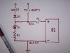
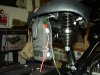
Here is my first upload of some pictures to this sight. The first one shows the battery box. The second one shows the wiring inside the box.
WHITE – white wire from motor
RED – to light, horn, switches, etc.
BLACK – black wire to motor or to ground
D1 – rectifier diode, I used Radio Shack 276-1141
Z1 – zener diode, 6.8v, 5w - 1N5342B
R1 – power resistor, 10ohm, 5watt, I used Radio Shack 271-132
F1 – fuse, I used a 5 amp fuse
B1 – 6v lead acid battery, I used a 1.3ah SLA
Battery box – 2.0x2.5x5.0 plastic Radio Shack project box
Mounting brackets – plastic conduit clamps from Home Depot
Attachments
-
 147 KB Views: 492
 -
 70.5 KB Views: 663
Last edited:
gberry50 - I looked at your pictures. You do indeed have a full wave rectifier but it looks like you have it wired as a half wave rectifier. A bridge rectifier contains four diodes but you are only using one of them. It will work that way, but you could use a single rectifier diode and get the same affect. From my tests, the half wave rectifier arrangment seems best for these motors anyway.
Hey, thanks a lot I tried a single diode but recieved less voltage than the one I have now . Didn't use the zenier diode or the resistor as the best I can get out of the mag
is 6.5 volts.Probably should use a fuse though. Could you send diagram for full wave
system just for the heck of it? by the way do you know of any one that has rewound the mag coil to boost the voltage?
is 6.5 volts.Probably should use a fuse though. Could you send diagram for full wave
system just for the heck of it? by the way do you know of any one that has rewound the mag coil to boost the voltage?
My volt meter reads zero at the battery at higher rpms is this normal and do you know of a fix as motor seems to get rough at about the same rpm like its not getting enough spark. I have checked the spark plug repeatedly and never seems to be fouled.
P.S. As you probably already discerned my experiance with electronics is rudementry
but I am pretty good with engines and this seem to be ignition related .
P.S. As you probably already discerned my experiance with electronics is rudementry
but I am pretty good with engines and this seem to be ignition related .
As implied in your original post if you try to use a full wave on these bikes the engine will not run. The wimpy ignition barely runs off the positive cycles and if you try to steal anything but negative cycles it dies.gberry50 - I looked at your pictures. You do indeed have a full wave rectifier but it looks like you have it wired as a half wave rectifier. A bridge rectifier contains four diodes but you are only using one of them. It will work that way, but you could use a single rectifier diode and get the same affect. From my tests, the half wave rectifier arrangment seems best for these motors anyway.
gberry50 – Do you have a battery installed yet? If not, you will have trouble getting a voltage reading off the system since it varies constantly. If no battery, you can put a capacitor across the meter leads and that will give you a stable reading of the peak voltage.
The zener diode is to prevent overcharging of the battery. If you have components that don’t like the high peak voltages, it may be useful even without the battery.
Assuming you don’t have a battery and your motor runs poorly when you hook the rectifier up, then reverse the two wires running to your rectifier. That will reverse your polarity and should fix the problem. If you are running LED bulbs, you may have to reverse their polarity also. If you have a battery, you will also have to reverse the battery leads.
I could do a diagram of a full wave setup but there are some other issues with it. The AC alternator output runs through the white wire and black wire. The black wire is grounded. If you hook up a full wave rectifier, you will have to insure that none of your lights, horn, or other electrical components are grounded. You will have to run a separate ground buss that is isolated from the chassis.
From everything that I’ve observed, a full wave charging system is not correct for these motors. The half wave is fairly weak, but it works and does not affect motor performance at all.
Here is another thought. If your only loads are LED bulbs, and you wire them all in the same correct direction, maybe you don’t even need the rectifier diode.
I can verify from experience that this is correct. The only thing diodes do is waste power. 9 LEDs in series with another 9 leds is perfect. Personally I prefer not to use the white wire for power or for kill. 68 LED 4 AA bike light does the trick for me.If your only loads are LED bulbs, and you wire them all in the same correct direction, maybe you don’t even need the rectifier diode.
I dont know if the picture loaded.I bought 35 of these packs they are 6v i put two together and got 12v they are rechargeable 1000mAh ni-cad.If anyone needs a set let me know.HD
Last edited:
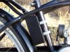
thanks for the post scotchmo. Yes I did install a 6v 1.2ahr sealed lead acid battery and it worked wellthe bulbs I am using will work between 3 and 9 volts so I'm ok with that.made the mistake of straping the battery to the luggage rack and killed it with vibration.got another and hung it from seat in an old cell phone holster see pic
P.S.For you speed junkies there are two seperate auctions on ebay for pocket bike
reed valves one over seas and one in the us .I ordered two as I have two engines
will post pics of mods.
Attachments
-
 136.3 KB Views: 312
gberry50 – It sounds like your negative ground battery/charging system is about the same as mine minus the regulator. It should work fine. Just to be cautious, and because I’m curious; could you check the voltage once in awhile with a DVM. Do it right after driving a few times without using the lights. Try it with the motor running. Since there is no regulator, it might be possible to overcharge the battery. But as long as the DVM is reading not much more than 7.0v, you should be good. The low end voltage reading should never be below 5.9v since that means that the battery is dead.
I’m trying to collect some information on the differences in these alternators. Could you also do this test; unhook the lead at the battery positive. Take that lead that comes from the rectifier and short it to the motor while the motor is idling. Does it kill the motor? It should slow down just a very small amount.
I’m trying to collect some information on the differences in these alternators. Could you also do this test; unhook the lead at the battery positive. Take that lead that comes from the rectifier and short it to the motor while the motor is idling. Does it kill the motor? It should slow down just a very small amount.
Pretty close. Find a bicycle generator set and you're got the headlight and tail light. The headlight bulb is 2.4W and the tail is .6W Most bike shops have replacements if you want to get a pair of bulbs to play with.I would like to try a 3watt led in headlight but I have learned on this forum that the output of lighting coil is only 3 watts is this true?
Lumotec p/n LT152 for the flanged headlight bulb, LT5000 for the threaded type.
Also, it's been mentioned already but i just want to re-state that you need the rectify the AC from the white wire to DC to charge the battery. Batteries don't like having AC shoved into them.
WHITE – white wire from motor
RED – to light, horn, switches, etc.
BLACK – black wire to motor or to ground
D1 – rectifier diode, I used Radio Shack 276-1141
Z1 – zener diode, 6.8v, 5w - 1N5342B
R1 – power resistor, 10ohm, 5watt, I used Radio Shack 271-132
F1 – fuse, I used a 5 amp fuse
B1 – 6v lead acid battery, I used a 1.3ah SLA
Battery box – 2.0x2.5x5.0 plastic Radio Shack project box
Mounting brackets – plastic conduit clamps from Home Depot
i cant find the zener diode 1n5342b at radio shack, is it a special order?
also are their any updates on this project im very interested on anyone's results.
in this configuration,what is the most watts total can the system use before the mag isn't charging the battery.
Radio Shack will not have that zener diode. You will have to locate a real electronics store. Check eBay or you could order online. Try running it without the zener regulator and resistor. Just eliminate that leg of the circuit. If the lead acid battery is big enough, it will be able to handle some overcharging. As long as it is not getting warm or gassing, it will probably survive.
If your average use is over 3 watts, you are probably running a deficit. That is OK as long as you drive with the lights off most of the time so that the battery will recharge.
If your average use is over 3 watts, you are probably running a deficit. That is OK as long as you drive with the lights off most of the time so that the battery will recharge.