DIY/DIY(Redundant?) Recumbent

GoldenMotor.com

cannonball2

Well-Known Member
Oct 28, 2010
3,682
221
63
Colonial Coast USA.
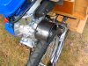
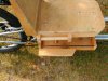
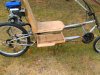
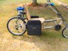
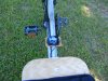
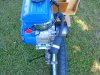
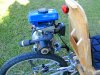
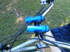
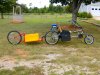
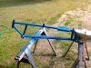
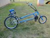
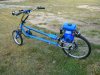
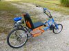
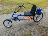
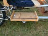
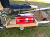
Fabbed the under seat carry tray. Has metal rails to allow bungee cord hook up. They were made from a weedeater solid driveshaft. It has a dedicated spot for a gallon metal fuel can. Tool kit will ride behind. When not touring, will carry whatever can be stuffed under there. Except for painting I think Im done with it. Has logged about 150mi, and Im finally pleased with all aspects of it. Less than 2 weeks from thought to build finish. My wife says Im posessed, I might agree.
 

Attachments

cannonball2

Well-Known Member
Oct 28, 2010
3,682
221
63
Colonial Coast USA.
More additions. Made a guard from a piece of metal tubing for the drive roller, PVC would work just as well. I ride a lot of dirt/sand/gravel roads with this one and it was throwing debris into the seat back. Not a problem with a standard bike. Also added a set of panniers in the only place I could find. They are far enough back so that they dont interfere with my seating, yet close to the weight center(me) that the loading of the bike doesnt change position much from what I am used to. I made the hangers interchangeable with some filler skirts that are quickly replaceable, so I dont have to answer questions like what happened to the toilet paper man?
 

Attachments

Elmo

New Member
Sep 3, 2009
748
4
0
Mississippi
That was really smart hanging the bags on the seat. If too much weight is on the very back of the bike it will unload the front wheel and make it easy to wash out in a turn on slick or loose surfaces. Don't ask me how I know about this. I really like your bike.
 

cannonball2

Well-Known Member
Oct 28, 2010
3,682
221
63
Colonial Coast USA.
Thanks for the kind compliments Elmo and Mike B! Have really enjoyed this build as it was more than just an engine install. I certainly learned about front end geometry, namely rake and trail with this one. It now has about 175 R&D miles and I guess its about done. Have worked out all the things I didnt like. I still need to make a hitch for it and see if the bike pulls the trailer OK. Oughta be about a mile long with the trailer. I originally built this for Deacons Expedition Impossibe, but in light of his situation now plan to use it for a few long distance camping trips this fall. Soon be time to take it apart for paint and seat pads.
 

cannonball2

Well-Known Member
Oct 28, 2010
3,682
221
63
Colonial Coast USA.
Still more changes. Replaced the modified stock box muffler with an exhaust designed to move the heat to the rear of the engine. Just a generic muffler coupled to a pipe fitting and a home made flange. What an improvement. Compare pics earlier in the thread to see the reposition. Took a little heat off the seat back. Have been riding in temps from the mid to hi 90s, and this was a relief. Wouldnt be a problem in cooler temps, might even be welcome this winter. Another added unexpected benefit was improved mid range torque. Also added a tach/hr meter, very helpful for determing optimum roller size. BTW I found the "headlights" at TSC for $1.99 ea. Anodized aluminum 9 led, with batteries. They are as bright as my bike intended headlights, they just dont flash. For a buck 99 who cares!
 

Attachments

cannonball2

Well-Known Member
Oct 28, 2010
3,682
221
63
Colonial Coast USA.
Last pieces of the puzzle. The trailer hitch and the trailer. This is the full traveling package. This bikes frame allowed the mounting of the hitch slightly above the axle, easing rear wheel removal. Makes a reasonably narrow profile. There is a second box that tops the first one doubling the space if necessary. If it wont fit in here some where I probably dont need it. This is a LONG package, thought I might need a panorama pic! Comes apart next week for finish and paint if I dont find something else it "needs".
 

Attachments

wayne z

Active Member
Dec 5, 2010
1,743
5
38
louisiana
So THAT's what you've been quietly busy with lately! Awesome build! Very simple and clean looking engine install too.

Makes my belt tranny FD thing look Rube Goldbergish in comparison.
 

cannonball2

Well-Known Member
Oct 28, 2010
3,682
221
63
Colonial Coast USA.
Thanks Wayne! Your build is anything but Rube Goldberg(who was he anyway). I admire the ability to have a low/hi, took a lot of thought on your part. I have been wrestling with a way to make a 2 sp direct drive, have several ideas but none are totally worked through. Have through a lot of testing optimized the roller in all operations but real slow riding, like down a rough gravel road. Need a smaller roller then. Making a stepped roller is no problem, shifting it is. Can move the engine, or move the roller, leaning on moving the roller. Any thoughts you/you all have would be appreciated.
 

wayne z

Active Member
Dec 5, 2010
1,743
5
38
louisiana
Thanks Wayne! Your build is anything but Rube Goldberg(who was he anyway). I admire the ability to have a low/hi, took a lot of thought on your part. I have been wrestling with a way to make a 2 sp direct drive, have several ideas but none are totally worked through. Have through a lot of testing optimized the roller in all operations but real slow riding, like down a rough gravel road. Need a smaller roller then. Making a stepped roller is no problem, shifting it is. Can move the engine, or move the roller, leaning on moving the roller. Any thoughts you/you all have would be appreciated.[/QUOT

A controllable stepped roller is a great idea!
If you use a 45 0r 60deg chamfer between steps, it should easily walk up or down steps while rolling, with even large diameter differences.
Look at an the varible speed fricton tranny hardware of an old Snapper self propelled mower, for parts and ideas about moving a stepped roller. Their fricton roller runs on a hex shaft and could be moved around on the shaft while being driven. You could take their roller and bolt a stepped one onto it, and use their hardware with some meds, I mean mods :~)
 
Last edited:

cannonball2

Well-Known Member
Oct 28, 2010
3,682
221
63
Colonial Coast USA.
What I have in mind still uses the homebuilt rollers. A piece of 5/8 jack shaft is center drilled in my lathe, and the faces trued, Then bolted to the crank to extend it as necesasary, maybe to 4" a 1.5" piece, maybe longer. I have a commercial mower spindle that is hollow with a 5/8 inside dia and a 1" outside. A keyway is cut inside the entire length. A key is added to the crank its entire length. The crank extension basically supports the key, which is the "driver" and the hollow spindle supportis it all. I have found in my case all the roller the drives the tire is 1.75" and I have driven very well with as little a 1". So a stepped roller with these or slightly larger dimensions is made and attatched to the outer shaft. A compression spring on the inboard crank side forces the roller to high constantly. A lever arrangement mounted to the engines pto face bolts, forces the roller to low when needed via some sort of lever control at the operator(like a shifter on the top tube maybe). I have the throw out bearing basically worked out for the accuator lever. Since low is to be used maybe only for take off and slow riding, there wouldn be a lot of shifting. However it could be flipped around and using a "big" small roller make a bike really go by shifting to an even bigger roller once wound out. I was thinking of my Schwinn, Its a fun bike and just used for tearing a round on. It tops at 38mph@ 5500rpm with a 2.4" roller, be fun to shift it to a 2.6 or 2.7 when wound out. This arrangement would have to be clutched to shift to take the load off the key. Just thoughts, now point out why it wont work.- before I start cutting metal!
 

wayne z

Active Member
Dec 5, 2010
1,743
5
38
louisiana
Might work ! you may have issues with the key, if fitted loosely enough to allow sliding. With a sideload the key may try to roll and pull the roller bore tight againstthe shaft opposite of the key. Maybe double opposing keys and ways.

Here's an idea for a different approach.
How about a fixed roller and a belt pulley on the crankshaft. and a side mount jackshaft on a plate bolted to the pto holes.
Then just use a rocking engine mount to engage either roller.
 

cannonball2

Well-Known Member
Oct 28, 2010
3,682
221
63
Colonial Coast USA.
Good idea. I had thought of something similar, would have to move the roller downstream of the engine some what for the belt length, but I dont see a problem. Think Ill mull this over, MUCH simplier. I tend to complicate things. Thanks wayne! BTW was just looking at my latest experimental roller and its only 1.5" wide drives very well.
 

cannonball2

Well-Known Member
Oct 28, 2010
3,682
221
63
Colonial Coast USA.
Forgot to add I had thought of a rocking roller plate cenerted around but not mounted to the crank, belt driven also. Didnt get far, need to give it more thought
 

cannonball2

Well-Known Member
Oct 28, 2010
3,682
221
63
Colonial Coast USA.
Got the frame in paint today. Perfect conditions 76F 33% humidity. Spent neary 5hrs hand filing the braze joints. Took several primings and sandings but came out acceptably. The color of the paint is darker than the pics show, pics dont do it justice. Any how its on the way.
 

Attachments