


I have modified half a dozen of these chinese motors for my son and his friends. I tried several mods to find combinations that worked well. We have no dyno or other fancy tools or software. These are cheap chinese motors, but they do respond to specific mods. The motors that ran the best were as follows:
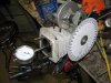
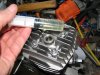
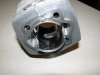
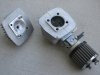
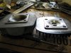
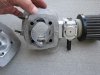
We modified the ports, head, intake, and the exhaust. The intakes are composed of V8 Breather filters from Checker Auto, Walbro 19mm carbs, and an adapter block made from phenolic. This adapter blends the 19mm diameter carb to the oval shape of the port and limits heat to the carb by being phenolic (previous versions were aluminum). The heads are slant heads. These heads have higher compression than the others to start with, so less machining is required and this retains their structural integrity. The heads are centered on the cylinders by putting machined alignment rods through the head/cylinders mounting holes. Two holes on either side of the bore are then drilled through the head into and through two of the cylinder fins. Roll pins are then pressed into the cylinders. The heads are re-drilled to clear the roll pins. This provides adequate alignment to keep the heads nearly concentric with the cylinders. The compression ratio is checked by sealing the piston/cylinder with grease, locking the piston at TDC, bolting on the head, and filling the head with oil to the bottom of the plug threads with a graduated 20cc syringe. The compression ratios (UCCR or CCR) can then be calculated. We machined our heads on the lathe (4-jaw chuck) for about 7cc combustion volume, or 10.4/1 UCCR, but raising it higher seems to be a good thing. The cylinders are ported. The exhausts are raised to 160 degrees duration (Open 100 degrees ATDC), and widened to a 1-1/4" oval. The transfers are only cleaned up NOT raised. Normally they are at about 114 degrees duration stock (open at about 123 degrees ATDC). This is about 23 degrees blow-down (123-100=23), which seems to make them "happy". The intake piston ports are lowered to provide about 130 degrees duration (Closes 65 degrees ATDC) and widened to 1-1/8", being careful not to get near the ring-end travel line. The port passages are opened up by cutting about 3/4" of the bottom of the cylinders and sharpening the bottom edges. This leaves about 3/4" of port passage wall left. The bottom passage side edge of the transfers are radiused by beveling the 90 degree corners slightly. This combination improved bottom/mid range torque while increasing top end over 7500 RPM. By the way, the RPM can be calculated by using the MPH and the motor/bike gearing and tire diameter. All edges of the ports were carefully filed to remove burrs and prevent ring hanging. The exhaust outlet was re-shaped to blend with the new port shape and polished. The same was done to the intake piston port without polishing. The exhaust header has an oval shape to match the exhaust port and is a 2" length of pipe to blend from this oval to a 1" round. The exhaust tubing is 1", and is connected to the rest of the exhaust by using 1" high-temp hose and clamps. The muffler is from a Banshee, cut almost in half and re-welded together (Banshee owners usually replace the original pipes/mufflers anyway). The ignition timing is verified by gluing a small degree wheel onto the flywheel, making a pointer from a small piece of safety wire under the nearby screw, and using a timing light. The timing is initially 20 degrees and reaches a max of 30 degrees at high RPM. The fuel we run is premium mixed with Klotz BeNol at 7oz per gallon which prevents bearing and piston damage. The compression ratio can be raised quite high on these 2-stroke motors unless you have a tuned pipe. The tuned pipe is a "sonic supercharger" capable of providing up to 5 to 7 lbs boost. As a result, the compression ratio will need to be low and the ignition timing will need retarding in the "boost region" (on-the-pipe) RPM. We have not balanced out motors as of yet, but plan to in the future. Here is a balancing we are proposing;
BALANCING YOUR BIKE MOTOR
by: DIYMark MBc Member (MotoredBikes.com: Motorized Bicycle Forum - Powered by vBulletin
edited by: JW
1) First decide on your balance percentage. The recommended is 55%.
2) Now you will need to weigh the total piston assembly - piston, rings, gudgeon pin, and record it.
3) Now weight each end of the rod with the corresponding bearing inserted into its race. Weight each end with the rod in a horizontal position. 2 accurate scales are ideal, but using one will work too and record it.
4) Add the piston assembly weight to the little end weight and times his amount by the balance percentage (keep in mined 55% equals 0.55) then add the big end weight to this number and you have balance mass.
BalanceMass = [( PistonAssym + RodLittleEnd) X 0.55 ] + RodBigEnd
5) Now make up a BalanceMass that weighs exactly as calculated above. You can make it from anything
such as nuts/bolts taped together or be fancy and machine a collar.
6) Inspect and re-machine the crankshaft counterbalances, if required, to obtain concentric components.
7) Fix the BalanceMass to the crank pin, press together, true, and mount your crank on 2 knife edge bearings that are level to the ground and parallel (2 steel rods will work).
8) You have to remove enough metal from the crank throws symmetrically (left/right) so that with the balance mass attached to the crank pin, you can turn the crank along the knife edges and no-matter what position you leave it at, it won't roll over to the heavier side. If the BalanceMass itself is too heavy, it will require removing an amount of metal from the BalanceMass and then removing amount/0.55 from the piston assembly. This requires careful thought. Although not necessary, if you want to be precise, use the density of steel/aluminum to calculate possible diameter holes and their depth to equal the desired weight to be drilled.
9) Once you are satisfied with the balance, dissemble the crank, clean and oil all components, press together, and true the crankshaft.
Although you cannot balance a single cylinder, this might get you a little closer so it doesn't give yer mits "lawnmower" effect at 8500 RPM. I'll give it a shot soon.
Oh, yea, please make corrections or give feedback so others can use this or other balancing techniques to balance their motors. It might be a good idea to keep it at the "shade tree mechanic" level (because I'm one), to make it possible. If you can get a good balance, share the tech info with us as to where to drill holes, what epoxy you filled the holes with and so-on.
Tools we have used include a lathe, dial indicator with holding fixture, mini 90 degree 1/8" rotary pneumatic grinder, 1/4" grinder, 10" degree wheel, numerous files, graduated syringe, timing light, 6" steel rule, and magic marker.
Attachments
-
 110.5 KB Views: 407
 -
 108.6 KB Views: 319
 -
 79.2 KB Views: 345
 -
 138.5 KB Views: 382
 -
6.8 KB Views: 184
Last edited:


 Now things get a little difficult.