

My First Project: Briggs 3 hp
- Thread starter discontinuuity
- Start date

That's a thunk right there! Now gonna be stuck in my head all day, lol.Maybe 1/4" cable clamps (essentially tiny u-bolts) to hold the bmx rim onto the spokes?
Really though, think you have cool idea that would work CC.
I used Solid Works CAD software to sketch up some motor mounts tonight. Hopefully I can get into my college's machine shop sometime in the next week and fab them up.

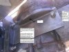
The picture shows the 3-piece mount from below. The darker piece will bolt up to the engine and the lighter pieces will clamp onto the bike frame. The clamp for the seat tube is on the right and the clamp for the down tube is on the left.
I have some spare hardware (like head bolts, etc.) from an old Briggs engine, so I figure that should be good enough for most of the mounting bolts. I'll still need to buy a few 1/4" and 3/8" bolts and various other hardware of course.
Edit: I'll check that out CC. I hadn't made any real plans on how I'll attach the rim to the wheel except maybe tying it on with wire. I might need to space it out a bit from the spokes though, so I'll need some kind of spacer in between.
Dan, any news on that special cylinder head? The one I have will most likely work fine, but that spark plug does limit me a bit on room.
Last edited:
Check the scrap pile a few times a week DC. Did find a 2 smoke head I thought would work for ya, but bolt pattern was different.
CC, could you elaborate some more on how you would use cable clamps? I'm having trouble tying it on with wire right now and I'm fishing around for ideas.
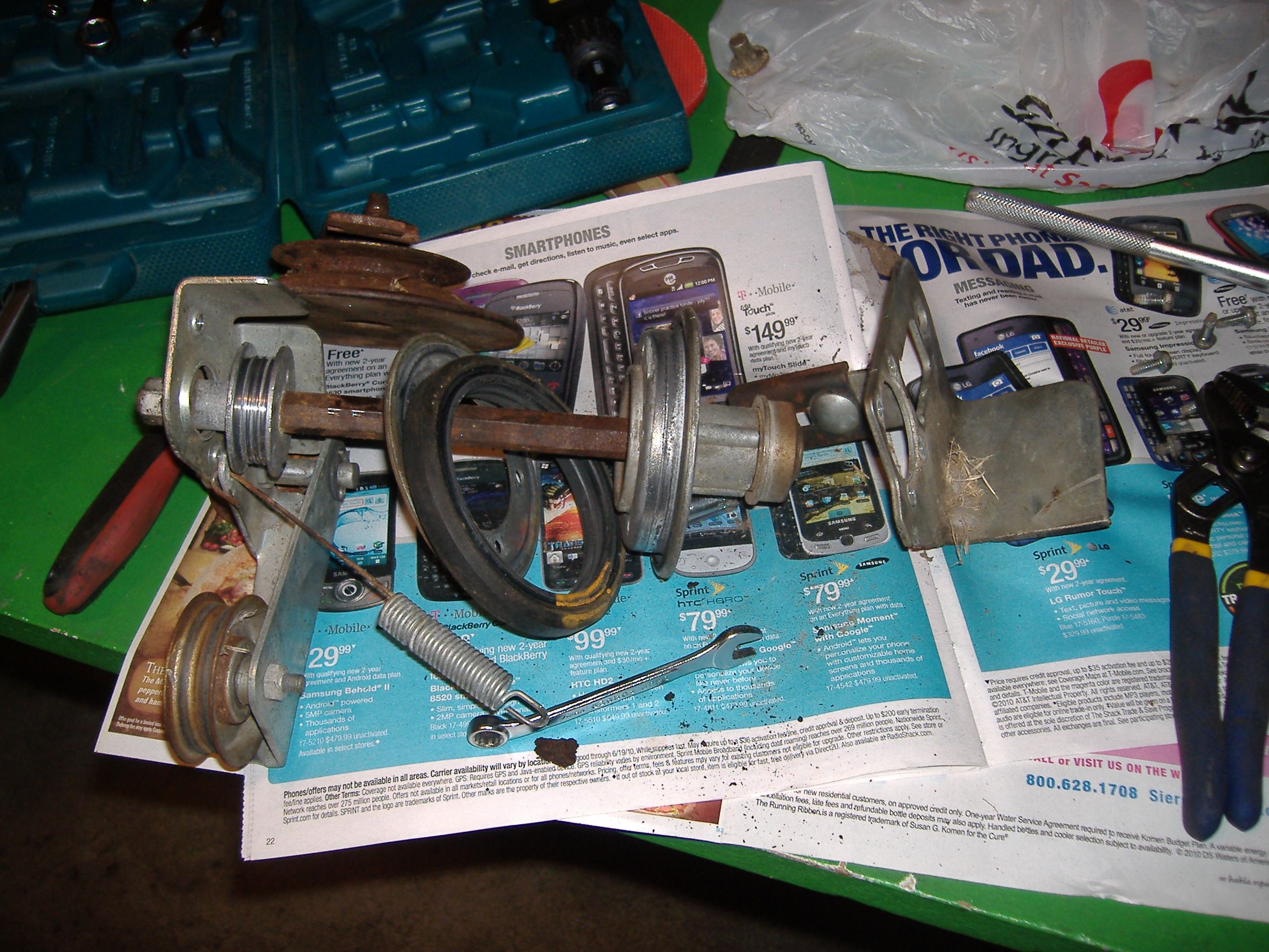
I am amazed, kudos, your well on your way. The elbow bend from the Tecumseh on a Briggs is what I did to avoid the seat post. The exhaust pipe to route out under a banana seat with some heat guards for my legs an out the back above the 25 inch knobby tire. I had tilted the engine and 15% back. It is better for the splash oil as I analyzed it as my engine I had in all its pieces and cleaned it up and cut the valves and seats at a machine shop for $20. I have picas that I can post of how I believe that the fork splash dips into oil from back portion and moves up and out 1/2 way forward before coming out of oil. This means the splash would only be greater as more time in the oil. The tilt forward would lessen this. As for oil getting into breather, there is a guard that would handle this. The valve tappets (mini push rods) are way above the oil level raise on the aft by the tilt and also the vale cam is between it and the oil sump.Took apart the lawn mower transmission tonight. It's a whole mess of weird pulleys, rusted bolts, and sticky bearings. I don't think I can use much of anything from it, since the shaft has a hexagonal cross section and the pulleys seem to be taper-fit. I'm not exactly sure about that, since most of the bolts are frozen and I can't get the two main pulleys off the shaft. I'll probably use a go-kart jack shaft and some pillow block bearings after all. At least I have a couple idler pulleys and a carburetor for free!
Speaking of finding things on the road, look what my roommate found walking around! We gave him a bowl of milk and a couch to sleep on, but he'll probably be going to the pound tomorrow since I'm allergic.

The one thing I noticed in the pic of the briggs you are using, which by the way I have an 80's era briggs I think same or 3.5 hp like yours, what is with the flywheel cover having a gap where stuff can get inside while riding it and cause major havoc.
Does anyone know if this type Briggs was used in such an application that it was covered?
Not to down play the briggs engines, but a tube muffler right over the gas tank with a breathing gas cap, that is not a current build by and means as for safety concerns. I got a separate gas tank and float carb that put the tank far away from the exhaust. So maybe they just had the flywheel spinning slightly expose. I know my 50's era Briggs with coil rope pull, no recoil, spins around without any guard. That’s the way those old cast iron ones were made then.
I will later get a pic to post of my part I mfr myself to cover up that gap. I had use of a work shop with everything and weld TIG which ended before I thought to make this cover. It can be done with a vise, couple of pieces of angle iron and sheet metal that I bend in a make shift brake press. I used two mounting points, one where the engine already has a threaded hold by the cylinder cooling shroud and one of the engine mounting holes. I also used a dremel with cut off wheel, hack saw, and large sheet metal cutters, but the cutters not all that necessary. Careful hack saw with fine tooth blade could do all the cutting.

Thanks for the info MT. I took off the cover the other day and cleaned out a few leaves. I think you're saying that it's possible for debris to foul the ignition, right? Do these have a points ignition or just a regular magneto/coil? Either way I probably won't mod the engine until I get the bike up and running.
I had the same thought about the exhaust and the gas tank. My plan is to use the Tecumseh carb and mount a tank on the top tube for a gravity feed. I'll make an exhaust pipe out of threaded iron pipe and fittings from the hardware store and wire it to the rear cargo rack I have lying around, with the stock muffler sitting out back. Hopefully I won't need to make a heat guard, but I've got some sheet metal and rivets if need be.
I'm about halfway done with the motor mounts, but I'm a bit stuck because my new work schedule prevents me from going into the machine shop when it's open. I'll probably have to pay someone to finish it for me.
I'm also a bit stuck on the rear pulley, but I'm making progress. If that doesn't work out I may switch to a simple chain setup with a jackshaft, but I'd rather stick with belts to cut down on the noise.
I imagine you already know this there is a universal electronic ignition for these motors. If memory serves me right Tacompsy and Briggs had the same point gap of 20 thousands. there is a universal ignition that works on both of them.
Universal Transistorized Ignition Modules
Universal Transistorized Ignition Modules
Very cool ignition module. I'll definitely check that out, especially if the current system breaks. Although I think my flywheel might have more than one magnet, which would make sense why it needs the points. So I'm not sure if it will work.
They were made to upgrade and replace all points! just ask them. They wire directly into you existing magneto to completely by pass the points..
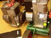
I'D BE REPLING TO THE LAST IN THE THREAD, BUT THE PICS, 1ST OF TWO ARE ALREADY HERE.Got some photos of the engine sitting on the frame, without motor mounts. I'm thinking about mounting it tilted forward a bit, but I'm not sure if that would screw up the oiling system. Maybe I can modify the oil slinger to make it work? Or I could tilt it the other way, so that the cam and oil slinger are under the oil level.
Tilting it would give me better clearance for the spark plug and the carburetor, but I would have to get a special intake pipe either way.
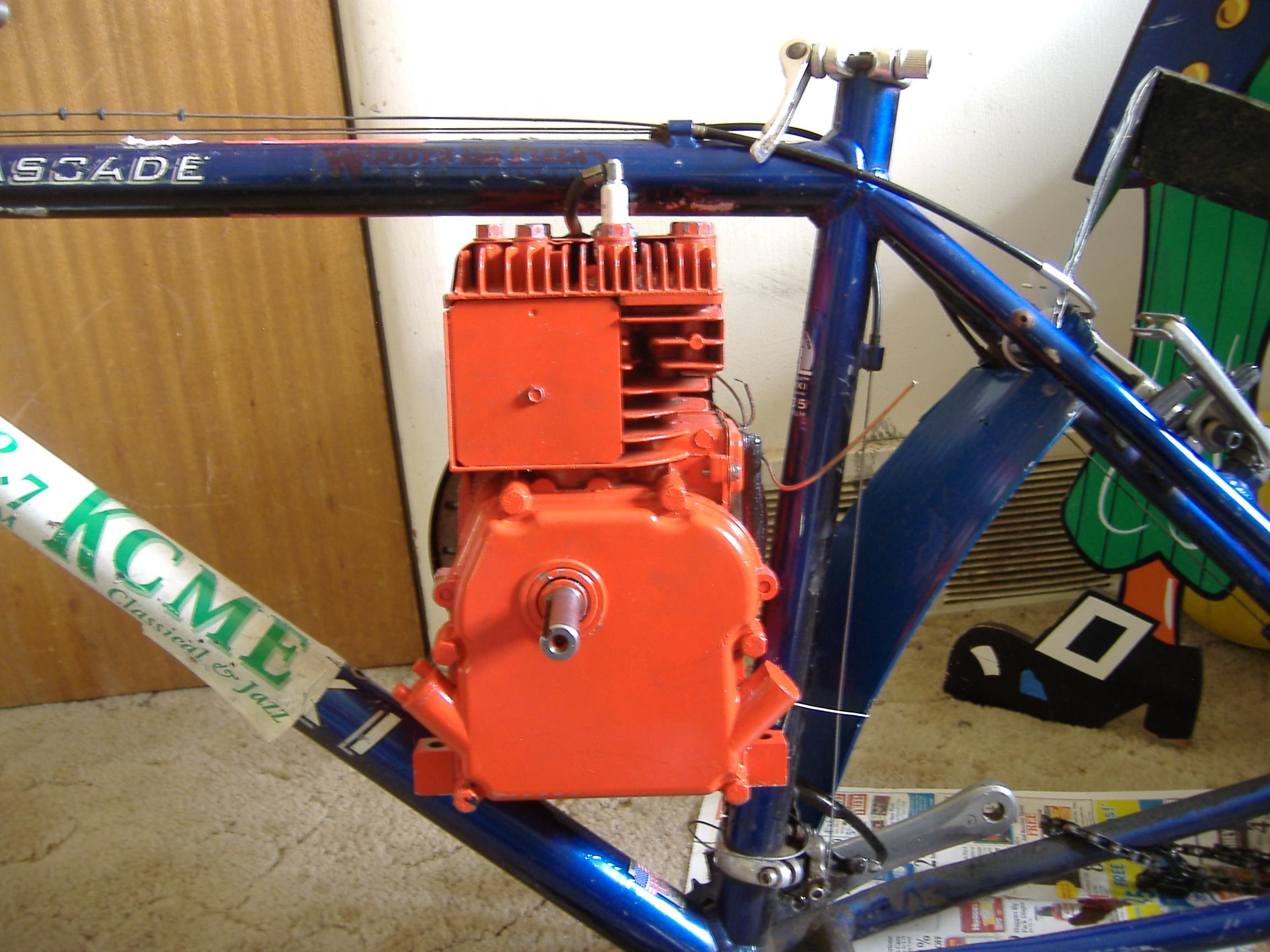
The first of two pics of your bike frame with engine not tilted, see:
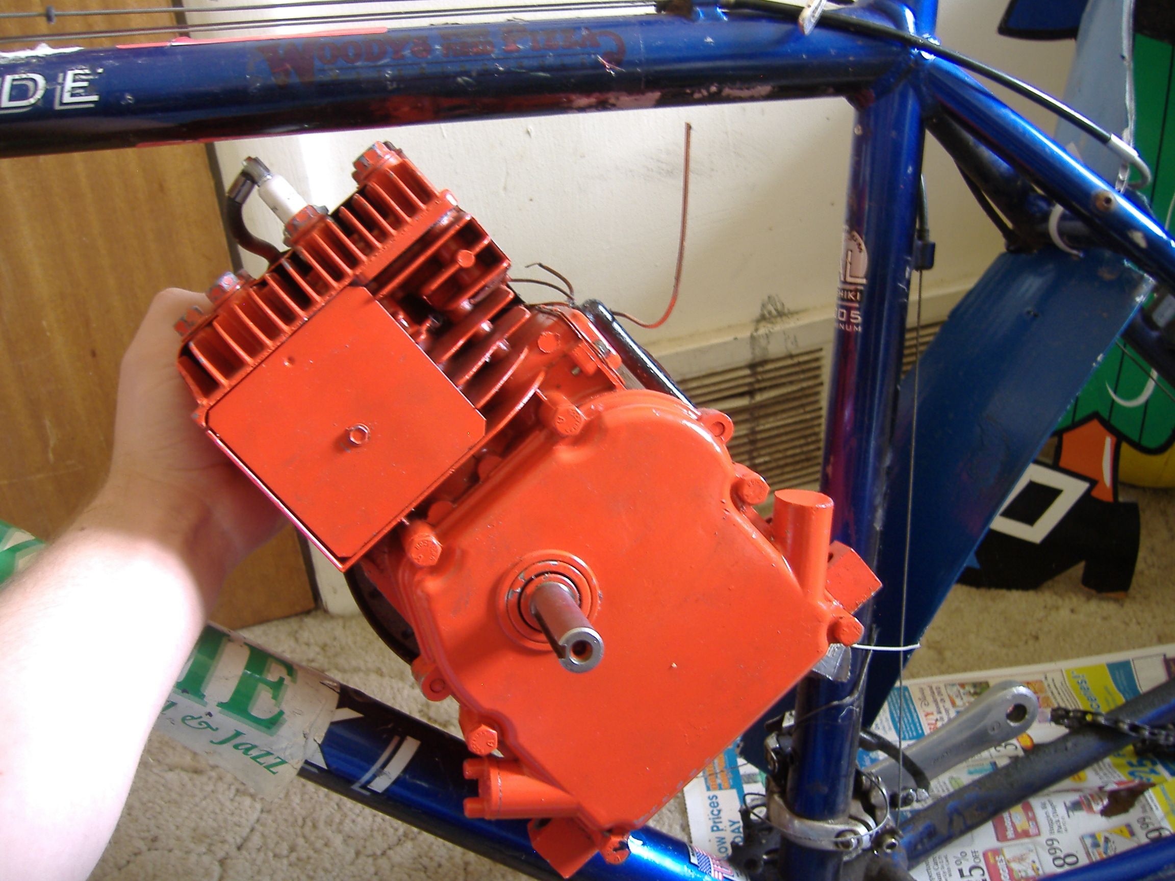
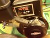
FLYWHEEL AN COVER EDGE FORWARD CURVED SHAPE INLINE WITH CRANK SHAFT UP AND TO THE LEFT
This is what I am talking about. You can see the edge of the recoil pull start/flywheel cover edge only.
Yes edge only, there is no cover in the roughly half moon shaped area, it exposes as you can see the magnet or opposing weight on the flywheel.
I can contact Briggs directly or email and check on this, I guess I sometimes get lazy and well I already made a cover, hope no adverse effect. Only since the governor linkage cannot go around a bend with the elbow of the Techumseh adaption to make engine intake fit frame, I am not concerned about air vane being adversely affected. I remove the air vane anyway. The air flow cooling is what I am concerned about. I think the fins on the flywheel pull the air through the perforated finger guard by the recoil pull start of the flywheel cover, so I feel that no problem there, but will see what they say.
Another web site to check Hit N Miss Enterprises Antique Gas Engines and Parts Hit & Miss Enterprises they have sales but also free info and list serv too. Lots of pics old antique engines.
As for two magnets, no just a fake counter weight.
Rivets of some type, two of them you can also see. This probably means that this is the magnet portion showing. You can put a piece of iron near it to tell, but I would think the non magnet counter weight is just machined along with the rest of the part in mfg. The magnet added later needed to be riveted on.
Handy to know also, put the non magnet counter weight rotated to opposite the magneto lapped metal induction area with an ordinary piece of printer paper. I use it one or two thicknesses. Then I only loosen the two screws holding the magneto in place just enough so you can push the magneto close to the flywheel counter weight.
Then while holding it there tighten up the two screws. Turn the flywheel and the paper comes out stiffly and hopefully the magnet and the counter weight of the flywheel both are very close to the magneto when the flywheel rotates. Too far away and you don't get a very good spark. Try to do this adjustment without this method and especially with the magnet adjacent to the magneto and it just get pulled in and stuck to the magneto.
I use fine emery cloth to sand off both the magneto lapping two curved areas, but only lightly and also the magnet to help with better spark. A point file between the point, or very thin and fine emery cloth folded with abrasive area out on both side between point with closed position do this. Sand slightly and re-gap to help remove point pits, burns, uneven surfaces to get hotter spark.
To reply to the mentioning of points, they are under the cover of the flywheel with a thin metal cover where the low tension lead comes out (goes to kill switch to ground). There is no coil, just the magneto. No rotor as in a multi cylinder engine, just a little shaved spot on the crank shaft by the points.
A little rod goes into the recess and allows the points to come apart. At compression stroke about 8 degrees before top dead center (point gap the .020 inch determines) the shaved spot allows a spring tensioned one side of the points to move outward and break contact with the opposite side of the contact points.
At the time the points open the grounded movable side of the points through a copper or tinned braided wire going to a screw with external tooth start lock washer to ground opens the short to the magneto's primary coil. To clarify, the opening of this short to ground actually stops the charging circuit to the primary. This then causes the field collapse and a flyback effect transfers a large voltage on the magneto's secondary (high tension to spark plug). The flyback effect is same as a battery powered coil, point open and 12 volts no longer on the primary, secondary high tension sparks.
A machine shop is definitely handy and I just can't afford to be going there with fees on going. The welding is just something not sufficient to do at home. I could make jewelry with the small oxy mapp gas stuff, but not much else.
Thinking the post somewhere else on the site about gas tank from two small empty propane tanks and the problem with weld/braze ect and leak problem. I thought of removing an old small pony scuba aluminum 13 cubic foot tank I have from service (note 13 CF at 3000 PSI). I would adapt it to hold gasoline for a motor bike gravity feed to carb bowl system. Size volume is about 1 liter I think. You would not have to be concerned much about strength as it is heavy weight aluminum.
Ah, last to mention I have to see about screens I got at HW store for vents and to adapt to guard muffler and pipe. I pick from trash an old stainless steel BBQ and to use the metal already formed nicely to cover moving parts (chain guard, belt, jack shaft ect).
Measure Twice

I'D BE REPLING TO THE LAST IN THE THREAD, BUT THE PICS, 1ST OF TWO ARE ALREADY HERE.
The first of two pics of your bike frame with engine not tilted, see:
FLYWHEEL AN COVER EDGE FORWARD CURVED SHAPE INLINE WITH CRANK SHAFT UP AND TO THE LEFT
This is what I am talking about. You can see the edge of the recoil pull start/flywheel cover edge only.
Yes edge only, there is no cover in the roughly half moon shaped area, it exposes as you can see the magnet or opposing weight on the flywheel.
I can contact Briggs directly or email and check on this, I guess I sometimes get lazy and well I already made a cover, hope no adverse effect. Only since the governor linkage cannot go around a bend with the elbow of the Techumseh adaption to make engine intake fit frame, I am not concerned about air vane being adversely affected. I remove the air vane anyway. The air flow cooling is what I am concerned about. I think the fins on the flywheel pull the air through the perforated finger guard by the recoil pull start of the flywheel cover, so I feel that no problem there, but will see what they say.
Another web site to check Hit N Miss Enterprises Antique Gas Engines and Parts Hit & Miss Enterprises they have sales but also free info and list serv too. Lots of pics old antique engines.
As for two magnets, no just a fake counter weight.
Rivets of some type, two of them you can also see. This probably means that this is the magnet portion showing. You can put a piece of iron near it to tell, but I would think the non magnet counter weight is just machined along with the rest of the part in mfg. The magnet added later needed to be riveted on.
Handy to know also, put the non magnet counter weight rotated to opposite the magneto lapped metal induction area with an ordinary piece of printer paper. I use it one or two thicknesses. Then I only loosen the two screws holding the magneto in place just enough so you can push the magneto close to the flywheel counter weight.
Then while holding it there tighten up the two screws. Turn the flywheel and the paper comes out stiffly and hopefully the magnet and the counter weight of the flywheel both are very close to the magneto when the flywheel rotates. Too far away and you don't get a very good spark. Try to do this adjustment without this method and especially with the magnet adjacent to the magneto and it just get pulled in and stuck to the magneto.
I use fine emery cloth to sand off both the magneto lapping two curved areas, but only lightly and also the magnet to help with better spark. A point file between the point, or very thin and fine emery cloth folded with abrasive area out on both side between point with closed position do this. Sand slightly and re-gap to help remove point pits, burns, uneven surfaces to get hotter spark.
To reply to the mentioning of points, they are under the cover of the flywheel with a thin metal cover where the low tension lead comes out (goes to kill switch to ground). There is no coil, just the magneto. No rotor as in a multi cylinder engine, just a little shaved spot on the crank shaft by the points.
A little rod goes into the recess and allows the points to come apart. At compression stroke about 8 degrees before top dead center (point gap the .020 inch determines) the shaved spot allows a spring tensioned one side of the points to move outward and break contact with the opposite side of the contact points.
At the time the points open the grounded movable side of the points through a copper or tinned braided wire going to a screw with external tooth start lock washer to ground opens the short to the magneto's primary coil. To clarify, the opening of this short to ground actually stops the charging circuit to the primary. This then causes the field collapse and a flyback effect transfers a large voltage on the magneto's secondary (high tension to spark plug). The flyback effect is same as a battery powered coil, point open and 12 volts no longer on the primary, secondary high tension sparks.
A machine shop is definitely handy and I just can't afford to be going there with fees on going. The welding is just something not sufficient to do at home. I could make jewelry with the small oxy mapp gas stuff, but not much else.
Thinking the post somewhere else on the site about gas tank from two small empty propane tanks and the problem with weld/braze ect and leak problem. I thought of removing an old small pony scuba aluminum 13 cubic foot tank I have from service (note 13 CF at 3000 PSI). I would adapt it to hold gasoline for a motor bike gravity feed to carb bowl system. Size volume is about 1 liter I think. You would not have to be concerned much about strength as it is heavy weight aluminum.
Ah, last to mention I have to see about screens I got at HW store for vents and to adapt to guard muffler and pipe. I pick from trash an old stainless steel BBQ and to use the metal already formed nicely to cover moving parts (chain guard, belt, jack shaft ect).
Measure Twice
This web site has lots of valuable info.
Outdoor Power Equipment Information
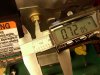
For my help in choosing a v belt (be sure to know that your measurement is for outside diameter!).
I measured with a thin piece of wire around the pulleys and that give inside diameter. Most of what I've seen list the spec for outside diameter. The wire I use got inside dimension and I couldn't find any conversion that did the math simply. If some one knows how for an easy way to change from inside to outside dimension let me know. Better yet all though I have tried find an automatic program on the web, like for F or C temp ect. Of course temp scale is something I know easy so that is why murphys has it easily found on the web.
Main Belts Reference Listing
also the carb your using see it there and info in theory how they work with cut away views etc.
Small Engine Equipment Troubleshooting, Repairs and Safety
this one looked like the one you have but only as far as I can tell with the shape of primer bulb
many other under repair see all the carbs with names and pics
repairs also shows the Briggs new pointless version magneto.
Disassembly of Tecumseh Series 9 Carburetor 632747
Briggs Engine 125K02 0137 Ignition System
Some chain saw spark plugs are shorter height and I got a plug that fit the temperature range, just a little cooler and it now fits better on the bike frame without shorting. It is changed from a J17LM Champion to a RCJ7Y Champion.
ChampionSparkplugs.com - Application Search Results RCJ7Y Champion Heat Range 7
So I went from 17 down to 7, but that cooler safer and you can damage an engine worse by too much non efficiency to remove heat with a hotter plug. Fowling with too cool happens, but that isn't as bad. The range Champion has for Automotive/Small Engine/Ordinance is 1 to 25 some I don't think I have varied too much cooler. I sort of wondered why list for ordinance when it is not a controlled explosion as in engines, and beside one time use? Only thing I could think is that too hot a spark may mean the way the fuel detonates may not fully burn as well so less of an explosion. Champion has three more groups that have a range up to 99. (Remember as I have noted that one mfr heat range number is not an equivalent to any other mfr necessarily and often they are not equivalent).
Hope this is of use
Measure Twice
BETTER WEB SITE FOR ALL AGES ENGINE REPAIR SEE:I'D BE REPLING TO THE LAST IN THE THREAD, BUT THE PICS, 1ST OF TWO ARE ALREADY HERE.
The first of two pics of your bike frame with engine not tilted, see:
FLYWHEEL AN COVER EDGE FORWARD CURVED SHAPE INLINE WITH CRANK SHAFT UP AND TO THE LEFT
This is what I am talking about. You can see the edge of the recoil pull start/flywheel cover edge only.
Yes edge only, there is no cover in the roughly half moon shaped area, it exposes as you can see the magnet or opposing weight on the flywheel.
I can contact Briggs directly or email and check on this, I guess I sometimes get lazy and well I already made a cover, hope no adverse effect. Only since the governor linkage cannot go around a bend with the elbow of the Techumseh adaption to make engine intake fit frame, I am not concerned about air vane being adversely affected. I remove the air vane anyway. The air flow cooling is what I am concerned about. I think the fins on the flywheel pull the air through the perforated finger guard by the recoil pull start of the flywheel cover, so I feel that no problem there, but will see what they say.
Another web site to check Hit N Miss Enterprises Antique Gas Engines and Parts Hit & Miss Enterprises they have sales but also free info and list serv too. Lots of pics old antique engines.
As for two magnets, no just a fake counter weight.
Rivets of some type, two of them you can also see. This probably means that this is the magnet portion showing. You can put a piece of iron near it to tell, but I would think the non magnet counter weight is just machined along with the rest of the part in mfg. The magnet added later needed to be riveted on.
Handy to know also, put the non magnet counter weight rotated to opposite the magneto lapped metal induction area with an ordinary piece of printer paper. I use it one or two thicknesses. Then I only loosen the two screws holding the magneto in place just enough so you can push the magneto close to the flywheel counter weight.
Then while holding it there tighten up the two screws. Turn the flywheel and the paper comes out stiffly and hopefully the magnet and the counter weight of the flywheel both are very close to the magneto when the flywheel rotates. Too far away and you don't get a very good spark. Try to do this adjustment without this method and especially with the magnet adjacent to the magneto and it just get pulled in and stuck to the magneto.
I use fine emery cloth to sand off both the magneto lapping two curved areas, but only lightly and also the magnet to help with better spark. A point file between the point, or very thin and fine emery cloth folded with abrasive area out on both side between point with closed position do this. Sand slightly and re-gap to help remove point pits, burns, uneven surfaces to get hotter spark.
To reply to the mentioning of points, they are under the cover of the flywheel with a thin metal cover where the low tension lead comes out (goes to kill switch to ground). There is no coil, just the magneto. No rotor as in a multi cylinder engine, just a little shaved spot on the crank shaft by the points.
A little rod goes into the recess and allows the points to come apart. At compression stroke about 8 degrees before top dead center (point gap the .020 inch determines) the shaved spot allows a spring tensioned one side of the points to move outward and break contact with the opposite side of the contact points.
At the time the points open the grounded movable side of the points through a copper or tinned braided wire going to a screw with external tooth start lock washer to ground opens the short to the magneto's primary coil. To clarify, the opening of this short to ground actually stops the charging circuit to the primary. This then causes the field collapse and a flyback effect transfers a large voltage on the magneto's secondary (high tension to spark plug). The flyback effect is same as a battery powered coil, point open and 12 volts no longer on the primary, secondary high tension sparks.
A machine shop is definitely handy and I just can't afford to be going there with fees on going. The welding is just something not sufficient to do at home. I could make jewelry with the small oxy mapp gas stuff, but not much else.
Thinking the post somewhere else on the site about gas tank from two small empty propane tanks and the problem with weld/braze ect and leak problem. I thought of removing an old small pony scuba aluminum 13 cubic foot tank I have from service (note 13 CF at 3000 PSI). I would adapt it to hold gasoline for a motor bike gravity feed to carb bowl system. Size volume is about 1 liter I think. You would not have to be concerned much about strength as it is heavy weight aluminum.
Ah, last to mention I have to see about screens I got at HW store for vents and to adapt to guard muffler and pipe. I pick from trash an old stainless steel BBQ and to use the metal already formed nicely to cover moving parts (chain guard, belt, jack shaft ect).
Measure Twice
This web site has lots of valuable info.
Outdoor Power Equipment Information
For my help in choosing a v belt (be sure to know that your measurement is for outside diameter!).
I measured with a thin piece of wire around the pulleys and that give inside diameter. Most of what I've seen list the spec for outside diameter. The wire I use got inside dimension and I couldn't find any conversion that did the math simply. If some one knows how for an easy way to change from inside to outside dimension let me know. Better yet all though I have tried find an automatic program on the web, like for F or C temp ect. Of course temp scale is something I know easy so that is why murphys has it easily found on the web.
Main Belts Reference Listing
also the carb your using see it there and info in theory how they work with cut away views etc.
Small Engine Equipment Troubleshooting, Repairs and Safety
this one looked like the one you have but only as far as I can tell with the shape of primer bulb
many other under repair see all the carbs with names and pics
repairs also shows the Briggs new pointless version magneto.
Disassembly of Tecumseh Series 9 Carburetor 632747
Briggs Engine 125K02 0137 Ignition System
Some chain saw spark plugs are shorter height and I got a plug that fit the temperature range, just a little cooler and it now fits better on the bike frame without shorting. It is changed from a J17LM Champion to a RCJ7Y Champion.
ChampionSparkplugs.com - Application Search Results RCJ7Y Champion Heat Range 7
So I went from 17 down to 7, but that cooler safer and you can damage an engine worse by too much non efficiency to remove heat with a hotter plug. Fowling with too cool happens, but that isn't as bad. The range Champion has for Automotive/Small Engine/Ordinance is 1 to 25 some I don't think I have varied too much cooler. I sort of wondered why list for ordinance when it is not a controlled explosion as in engines, and beside one time use? Only thing I could think is that too hot a spark may mean the way the fuel detonates may not fully burn as well so less of an explosion. Champion has three more groups that have a range up to 99. (Remember as I have noted that one mfr heat range number is not an equivalent to any other mfr necessarily and often they are not equivalent).
Hope this is of use
Measure Twice
I contacted Briggs and Stratton and checked with a few shops too on the missing part of the flywheel cover on this pictured and my engine also. My engine 80202-0430-01.
-------------------------------------------------------------------------------------------------
see my post I was wrong post #40 Today Friday July 30th 2010 2:33 PM my time
-------------------------------------------------------------------------------------------------
-------------------------------------------------------------------------------------------------
From Measure Twice I was wrong Briggs has some parts Guard Flywheel
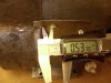
Important the different year model Briggs and Stratton 3hp side shaft engine missing the Guard Flywheel I found I was wrong and some are available. I have measured the mounting spacing holes are different from different Briggs 3hp’s so check with shop for your specific model.
I was at MMI in Sunnyvale CA and they had an edger with a Briggs 3 hp engine on it. I saw how they have a separate part to guard the flywheel that is used in addition to the flywheel cover. Cheap about $5 and can be ordered for both the new engine that was on the newer Brigg that was on the edger they were selling and also my Briggs 80202-0430 model 3 hp engine.
The 80202-0430 uses a 220971 part number. I already posted pic of what I made for the part so I am not bothering to buy one, those who have the part missing may want to investigate if they can get the part if needed rather than mfr their own as I did. I called Brigg direct and they could not get the info, also other shops as well, but just the recent thing happens I got a part in the MMI store a spark arrester type muffler and got looking what was on the show room floor.
================================================== =======================
For my old 80’s era Briggs 80202-0430 model 3 hp engine $2.85 on Briggs Link
Buy Repair Parts - Briggs & Stratton
================================================== =======================
For the New Briggs 3 hp engine I saw in the shop don’t know what model Briggs Engine but check your model and if you give either part number and your specific model engine, I would ask to see which of these or other would fit. Both parts cannot. I measured on both new and old engine and they are different.
part $4.25
Buy Repair Parts - Briggs & Stratton
Small Engines, Lawn Mower Engines and Generators by Briggs & Stratton
MMI Power Equipment | Locations
-------------------------------------------------------------------------------------------------
-------------------------------------------------------------------------------------------------
STRIKE OUT!!!!! - Correction there is no part you can buy and there never was, except to buy a whole new flywheel cover, which they don't make anymore.
-------------------------------------------------------------------------------------------------
The guy at the shop said that what I had done to fix it makes sense. When I looked at the corresponding area with the half moon shape on the flywheel cover near the intake an exhaust ports, I can see where it is a piece of sheet metal tack welded on. Most of the old covers must lose the forward one more easily as much as I can tell from rusting. It is imperative to cover this area for safety of user and the engine itself. The airflow does require it to be there for the design in the cooling as well. The air goes through the suction of the fins on the flywheel and across the fins on the cylinder and the turns right angle back when hitting the square plate that screws on with one screw to cover the cylinder fins. It is removable to allow access to clean grass clipping and debris out of the fins on the cylinder during maintenance.
If you make the repair as close to original to the vacant sheet metal part of the flywheel cover that leaves this dangerous gap, it would be by welding sheet metal back where it is suppose to be.
My time was up for membership where I was doing TIG welding, so I opted to fabricate a part that fits on by using existing threads in the engine and mounts. I have the pictures see attached.
Measure Twice
======================================================
-------------------------------------------------------------------------------------------------
see my post I was wrong post #40 Today Friday July 30th 2010 2:33 PM my time
-------------------------------------------------------------------------------------------------
-------------------------------------------------------------------------------------------------
From Measure Twice I was wrong Briggs has some parts Guard Flywheel
Important the different year model Briggs and Stratton 3hp side shaft engine missing the Guard Flywheel I found I was wrong and some are available. I have measured the mounting spacing holes are different from different Briggs 3hp’s so check with shop for your specific model.
I was at MMI in Sunnyvale CA and they had an edger with a Briggs 3 hp engine on it. I saw how they have a separate part to guard the flywheel that is used in addition to the flywheel cover. Cheap about $5 and can be ordered for both the new engine that was on the newer Brigg that was on the edger they were selling and also my Briggs 80202-0430 model 3 hp engine.
The 80202-0430 uses a 220971 part number. I already posted pic of what I made for the part so I am not bothering to buy one, those who have the part missing may want to investigate if they can get the part if needed rather than mfr their own as I did. I called Brigg direct and they could not get the info, also other shops as well, but just the recent thing happens I got a part in the MMI store a spark arrester type muffler and got looking what was on the show room floor.
================================================== =======================
For my old 80’s era Briggs 80202-0430 model 3 hp engine $2.85 on Briggs Link
Buy Repair Parts - Briggs & Stratton
================================================== =======================
For the New Briggs 3 hp engine I saw in the shop don’t know what model Briggs Engine but check your model and if you give either part number and your specific model engine, I would ask to see which of these or other would fit. Both parts cannot. I measured on both new and old engine and they are different.
part $4.25
Buy Repair Parts - Briggs & Stratton
Small Engines, Lawn Mower Engines and Generators by Briggs & Stratton
MMI Power Equipment | Locations
-------------------------------------------------------------------------------------------------
-------------------------------------------------------------------------------------------------
STRIKE OUT!!!!! - Correction there is no part you can buy and there never was, except to buy a whole new flywheel cover, which they don't make anymore.
-------------------------------------------------------------------------------------------------
The guy at the shop said that what I had done to fix it makes sense. When I looked at the corresponding area with the half moon shape on the flywheel cover near the intake an exhaust ports, I can see where it is a piece of sheet metal tack welded on. Most of the old covers must lose the forward one more easily as much as I can tell from rusting. It is imperative to cover this area for safety of user and the engine itself. The airflow does require it to be there for the design in the cooling as well. The air goes through the suction of the fins on the flywheel and across the fins on the cylinder and the turns right angle back when hitting the square plate that screws on with one screw to cover the cylinder fins. It is removable to allow access to clean grass clipping and debris out of the fins on the cylinder during maintenance.
If you make the repair as close to original to the vacant sheet metal part of the flywheel cover that leaves this dangerous gap, it would be by welding sheet metal back where it is suppose to be.
My time was up for membership where I was doing TIG welding, so I opted to fabricate a part that fits on by using existing threads in the engine and mounts. I have the pictures see attached.
Measure Twice
======================================================
I'D BE REPLING TO THE LAST IN THE THREAD, BUT THE PICS, 1ST OF TWO ARE ALREADY HERE.
The first of two pics of your bike frame with engine not tilted, see:
FLYWHEEL AN COVER EDGE FORWARD CURVED SHAPE INLINE WITH CRANK SHAFT UP AND TO THE LEFT
This is what I am talking about. You can see the edge of the recoil pull start/flywheel cover edge only.
Yes edge only, there is no cover in the roughly half moon shaped area, it exposes as you can see the magnet or opposing weight on the flywheel.
I can contact Briggs directly or email and check on this, I guess I sometimes get lazy and well I already made a cover, hope no adverse effect. Only since the governor linkage cannot go around a bend with the elbow of the Techumseh adaption to make engine intake fit frame, I am not concerned about air vane being adversely affected. I remove the air vane anyway. The air flow cooling is what I am concerned about. I think the fins on the flywheel pull the air through the perforated finger guard by the recoil pull start of the flywheel cover, so I feel that no problem there, but will see what they say.
Another web site to check Hit N Miss Enterprises Antique Gas Engines and Parts Hit & Miss Enterprises they have sales but also free info and list serv too. Lots of pics old antique engines.
As for two magnets, no just a fake counter weight.
Rivets of some type, two of them you can also see. This probably means that this is the magnet portion showing. You can put a piece of iron near it to tell, but I would think the non magnet counter weight is just machined along with the rest of the part in mfg. The magnet added later needed to be riveted on.
Handy to know also, put the non magnet counter weight rotated to opposite the magneto lapped metal induction area with an ordinary piece of printer paper. I use it one or two thicknesses. Then I only loosen the two screws holding the magneto in place just enough so you can push the magneto close to the flywheel counter weight.
Then while holding it there tighten up the two screws. Turn the flywheel and the paper comes out stiffly and hopefully the magnet and the counter weight of the flywheel both are very close to the magneto when the flywheel rotates. Too far away and you don't get a very good spark. Try to do this adjustment without this method and especially with the magnet adjacent to the magneto and it just get pulled in and stuck to the magneto.
I use fine emery cloth to sand off both the magneto lapping two curved areas, but only lightly and also the magnet to help with better spark. A point file between the point, or very thin and fine emery cloth folded with abrasive area out on both side between point with closed position do this. Sand slightly and re-gap to help remove point pits, burns, uneven surfaces to get hotter spark.
To reply to the mentioning of points, they are under the cover of the flywheel with a thin metal cover where the low tension lead comes out (goes to kill switch to ground). There is no coil, just the magneto. No rotor as in a multi cylinder engine, just a little shaved spot on the crank shaft by the points.
A little rod goes into the recess and allows the points to come apart. At compression stroke about 8 degrees before top dead center (point gap the .020 inch determines) the shaved spot allows a spring tensioned one side of the points to move outward and break contact with the opposite side of the contact points.
At the time the points open the grounded movable side of the points through a copper or tinned braided wire going to a screw with external tooth start lock washer to ground opens the short to the magneto's primary coil. To clarify, the opening of this short to ground actually stops the charging circuit to the primary. This then causes the field collapse and a flyback effect transfers a large voltage on the magneto's secondary (high tension to spark plug). The flyback effect is same as a battery powered coil, point open and 12 volts no longer on the primary, secondary high tension sparks.
A machine shop is definitely handy and I just can't afford to be going there with fees on going. The welding is just something not sufficient to do at home. I could make jewelry with the small oxy mapp gas stuff, but not much else.
Thinking the post somewhere else on the site about gas tank from two small empty propane tanks and the problem with weld/braze ect and leak problem. I thought of removing an old small pony scuba aluminum 13 cubic foot tank I have from service (note 13 CF at 3000 PSI). I would adapt it to hold gasoline for a motor bike gravity feed to carb bowl system. Size volume is about 1 liter I think. You would not have to be concerned much about strength as it is heavy weight aluminum.
Ah, last to mention I have to see about screens I got at HW store for vents and to adapt to guard muffler and pipe. I pick from trash an old stainless steel BBQ and to use the metal already formed nicely to cover moving parts (chain guard, belt, jack shaft ect).
Measure Twice
Attachments
-
 372.5 KB Views: 465
 -
 372.5 KB Views: 363
Last edited:
FEW MORE PICS OF FIX
I contacted Briggs and Stratton and checked with a few shops too on the missing part of the flywheel cover on this pictured and my engine also. My engine 80202-0430-01.
Correction there is no part you can buy and there never was, except to buy a whole new flywheel cover, which they don't make anymore. The guy at the shop said that what I had done to fix it makes sense. When I looked at the corresponding area with the half moon shape on the flywheel cover near the intake an exhaust ports, I can see where it is a piece of sheet metal tack welded on. Most of the old covers must lose the forward one more easily as much as I can tell from rusting. It is imperative to cover this area for safety of user and the engine itself. The airflow does require it to be there for the design in the cooling as well. The air goes through the suction of the fins on the flywheel and across the fins on the cylinder and the turns right angle back when hitting the square plate that screws on with one screw to cover the cylinder fins. It is removable to allow access to clean grass clipping and debris out of the fins on the cylinder during maintenance.
If you make the repair as close to original to the vacant sheet metal part of the flywheel cover that leaves this dangerous gap, it would be by welding sheet metal back where it is suppose to be.
My time was up for membership where I was doing TIG welding, so I opted to fabricate a part that fits on by using existing threads in the engine and mounts. I have the pictures see attached.
Measure Twice
======================================================
Another view of flywheel cover gap with text insertedFEW MORE PICS OF FIX
Measure Twice
PS other:
I found and ordered my muffler from a shop for a Briggs & Stratton part that has spark arrestor built into the muffler, hope that satisfies the state DMV for off roading
Attachments
-
 372.5 KB Views: 294
the right pic now......Another view of flywheel cover gap with text inserted
Measure Twice
PS other:
I found and ordered my muffler from a shop for a Briggs & Stratton part that has spark arrestor built into the muffler, hope that satisfies the state DMV for off roading
Measure Twice
Attachments
-
 104.1 KB Views: 350
From Measure Twice I was wrong Briggs has some parts Guard Flywheel
From Measure Twice I was wrong Briggs has some parts Guard Flywheel
Important the different year model Briggs and Stratton 3hp side shaft engine missing the Guard Flywheel I found I was wrong and some are available. I have measured the mounting spacing holes are different from different Briggs 3hp’s so check with shop for your specific model.
I was at MMI in Sunnyvale CA and they had an edger with a Briggs 3 hp engine on it. I saw how they have a separate part to guard the flywheel that is used in addition to the flywheel cover. Cheap about $5 and can be ordered for both the new engine that was on the newer Brigg that was on the edger they were selling and also my Briggs 80202-0430 model 3 hp engine.
The 80202-0430 uses a 220971 part number. I already posted pic of what I made for the part so I am not bothering to buy one, those who have the part missing may want to investigate if they can get the part if needed rather than mfr their own as I did. I called Brigg direct and they could not get the info, also other shops as well, but just the recent thing happens I got a part in the MMI store a spark arrester type muffler and got looking what was on the show room floor.
=========================================================================
For my old 80’s era Briggs 80202-0430 model 3 hp engine $2.85 on Briggs Link
Buy Repair Parts - Briggs & Stratton
=========================================================================
For the New Briggs 3 hp engine I saw in the shop don’t know what model Briggs Engine but check your model and if you give either part number and your specific model engine, I would ask to see which of these or other would fit. Both parts cannot. I measured on both new and old engine and they are different.
part $4.25
Buy Repair Parts - Briggs & Stratton
Small Engines, Lawn Mower Engines and Generators by Briggs & Stratton
MMI Power Equipment | Locations
PS
I will see if I can remove post that mentions parts unavailable by contacting admin at MotorBiicycling
MEASURE TWICE
====================================================
====================================================
Hi folks,
I've been lurking here a bit, gathering info on what kind of engine I could put on my old mountain bike. I can't afford one of the Huasheng/Honda 4-stroke kits right now, and I've heard all kinds of things about the Chinese 2-strokes exploding after a few miles. So when I saw a 3 hp Briggs & Stratton motor on craigslist for $30, I decided to build my own. My goal for this project is to keep the budget under $100.
My plan right now is to get the motor mounted in the frame, and figure other stuff out later. The engine doesn't quite fit, so I'm going to cut some notches in the bottom of the engine for clearance, near the bolt holes for mounting the engine. Then I'll make some motor mounts, either by sand-casting them out of aluminum or by borrowing a welder and fabbing them from steel. I'll probably have to re-route the intake and exhaust too, maybe going to a float-type carburetor.
For the transmission, I'm going with a belt drive like a Whizzer, with a smaller wheel rim as the rear pulley. I can either use a centrifugal clutch with a pulley or use an adjustable tensioner to engage or disengage the belt. With a 3.2" engine pulley this will give me a speed of 35 mph at 3,000 rpm. Not the best gear ratio, but maybe I'll add a jackshaft or a gear reduction later.
So, what do you think? Should I go with a centrifugal go-kart clutch or make my own manual friction clutch?
Attachments
-
 187.7 KB Views: 355
 -
 194.9 KB Views: 418
 -
 152.4 KB Views: 279
 -
 169.4 KB Views: 294
 -
 148.9 KB Views: 304