In frame Predator fricton drive build

GoldenMotor.com

wayne z

Active Member
Dec 5, 2010
1,743
5
38
louisiana
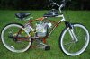
I just used the cheap tires that came with the bike. It seems that the short cone shape twists against the tire and wears them out faster than a cylindrical roller. I had a drive roller and an opposing idler roller. the tire wore away quickly on the drive side.
The bike was very top heavy with the rack mounted briggs. riding was no prob, but it was hard to keep upright when parked.
 

wayne z

Active Member
Dec 5, 2010
1,743
5
38
louisiana
Well, I had a new button knobbie on there for about 50 miles with the steel roller before I installed the stone. It slipped some when wet but the tire showed no wear in that time.
After I installed the stone, the knobs started wearing down quickly. Another 50 miles and the knobs are almost completly gone. Knobbies don't like FD.
I have a new set of Cityslicks, and they have a very square profile, may be better contact and less wear.
I want to run the knobbies down to slick and closey watch how the tire wears after that before I decide which roller I want to use with the new slicks.

One thing for sure, the stone roller is very reliable in grip. You can quickly and reliably accellerate from a stop with wet tires. I'm hoping that the squareish slicks will wear better than the knobbies enough to justify keeping the stone roller. It don't slip even in mud. I can set the roller pressure lighter and go easier on the throttleand prolly extend tire wear too.
 
Last edited:

happyvalley

New Member
Jul 24, 2008
784
1
0
upper Pioneer Valley
I have observed noticeable increased tire wear with a stone aggregate roller when used in all conditions but particularly accelerated if left on for any length of time on dry roads. Stands to reason, contact of a grinding wheel to rubber. One thing too about slicks is the casings aren't all that thick in bicycle tires. Couple of seasons ago I messed up one time by foolishly lowering a roller I thought had stopped turning onto a slick tire to lock it down.....needless to say it wore a spot down to the tire fabric in about two seconds.
 

cannonball2

Well-Known Member
Oct 28, 2010
3,682
221
63
Colonial Coast USA.
I have found the same to be true in both instances with my sanding belt roller. Grips like crazy in the wet, yet seems hard on the tire in the dry. Obviously water is a lubricant, and a "gritty" roller is best in the wet. When dry the smoothest surface on the roller seems to get the best bite, and is easiest on the tire. I see almost no powered rubber build up with a very smooth roller. The tires we have are not optimum for FD, they crown in the middle. I actually had the best drive with my nearly worn out cruiser tire becaue it had become nearly a flat section and the outer sections of the tread which were not worn began to take the load. Am impressed with the Thick Bricks because they can be run at a lower pressure, allowing the roller to grip the entire tread, and still support the bike and rider.
 

wayne z

Active Member
Dec 5, 2010
1,743
5
38
louisiana
Wayne,

I've read this thread till I'm seeing double looking for your pulley diameters. Do you recall what size pulleys you used in the transmission ?
Sure thing, glad to share the info. This tranny high ratio is taller that my 2 speed belt tranny build, and Ilike it better for lower rpm in cruise.
Low gear= 2.5 on motor, 5" on jackshaft.
Hi gear= 3" on motor,4" on jackshaft. The friction pully on the jackshaft, that drives the tire, is 3.5" dia.

Basicly, I used a spring loaded idler arm to tighten the low range belt as a manual clutch. I then mounted 2nd gea's pivoting idler assembly directly on the 1st gear idler arm.
 
Last edited:

motorhedfred

Member
Jul 31, 2009
421
17
18
United States
Ironic, I was trying to figure out some ratios this morning based on performance car 4-speed transmissions I'm familiar with from my muscle car days. One of my favorites for mild small block applications was a Saginaw wide ratio. It's 2nd gear was 2.02-1, 3rd was 1.35-1. Your's are roughly the same at 2-1 and 1.33-1.

I was thinking a 2" and 4" for low range, and a 3" and 4" for high range with a 3.5 or 4" drive roller on a 29" tire.

CB2 has me convinced that an oak roller is the shiznitz. I'm thinking thinner layers (1/2" ?) laminated with a waterproof glue or epoxy with the grain oriented in different directions like plywood. Stronger with more endgrain exposed around the circumference for better grip. Then maybe chuck it up in a lathe and turn some ribs in it for surface area.

Did you end up using your knurled metal roller ?
 

wayne z

Active Member
Dec 5, 2010
1,743
5
38
louisiana
Ironic, I was trying to figure out some ratios this morning based on performance car 4-speed transmissions I'm familiar with from my muscle car days. One of my favorites for mild small block applications was a Saginaw wide ratio. It's 2nd gear was 2.02-1, 3rd was 1.35-1. Your's are roughly the same at 2-1 and 1.33-1.

I was thinking a 2" and 4" for low range, and a 3" and 4" for high range with a 3.5 or 4" drive roller on a 29" tire.

CB2 has me convinced that an oak roller is the shiznitz. I'm thinking thinner layers (1/2" ?) laminated with a waterproof glue or epoxy with the grain oriented in different directions like plywood. Stronger with more endgrain exposed around the circumference for better grip. Then maybe chuck it up in a lathe and turn some ribs in it for surface area.

Did you end up using your knurled metal roller ?
Yes, I ran the knurled steel roller for about 600 miles. The knurls smoothed down pretty good after about 100 miles but it still works excellent in dry conditions. 600 miles on the same tire,and it still had about 1/2 of the tread depth left.
I then experimented with a grindstone roller. It had excellent grip in water and mud, but it wore the original tire down to the cords in about 60 miles. I changed back to the steel roller.

DSC_1541.JPG

That's a good idea about laminating an oak roller with maximum end grain exposure. I believe that the wood rollers grip better than the steel .
 
Last edited:

motorhedfred

Member
Jul 31, 2009
421
17
18
United States
Thanks for the compliment. The thought came to me as I was typing. I found that floor flanges for 3/8 iron pipe are about 3" OD and .590-.610 ID. Perfect for capping the ends of the roller and giving a solid metal connection to the shaft running through it.

Since I was planning on using a 5/8 keyed shaft anyway, this will work out great. I just need to drill them to 5/8 ID and get a keyway machined into them. 4 bolts passing through the wood leaves no chance of the roller slipping around the shaft.

Now I need to figure out a way to press it against the tire. Do you suggest something hinged so you can release the pressure if need be ?
 

dracothered

New Member
Jul 25, 2012
973
1
0
Howell, MI.
Here is an interesting thought that went through my mind as I was looking at your great setup. What if instead of friction drive you use the setup to run a chain drive on the other side?

Here is my idea with a crude sketch showing how it might work...


The Red line is the chain on the other side from the belt drive.
 

Attachments

wayne z

Active Member
Dec 5, 2010
1,743
5
38
louisiana
Here is an interesting thought that went through my mind as I was looking at your great setup. What if instead of friction drive you use the setup to run a chain drive on the other side?

Here is my idea with a crude sketch showing how it might work...


The Red line is the chain on the other side from the belt drive.
That's a great idea that would work. I have actualy thought of doing nearly the same idea, but with a chain primary. That small pully in my pic is actualy a flat idler to tighten the belt manualy for a clutch. The flat idler reverses direction but it would not have enough belt grip grip to drive the wheel chain, so a chain primary will work with this idea. In fact, there's a couple builds here that have experimented with a similar idea.
 

wayne z

Active Member
Dec 5, 2010
1,743
5
38
louisiana
Thanks for the compliment. The thought came to me as I was typing. I found that floor flanges for 3/8 iron pipe are about 3" OD and .590-.610 ID. Perfect for capping the ends of the roller and giving a solid metal connection to the shaft running through it.

Since I was planning on using a 5/8 keyed shaft anyway, this will work out great. I just need to drill them to 5/8 ID and get a keyway machined into them. 4 bolts passing through the wood leaves no chance of the roller slipping around the shaft.

Now I need to figure out a way to press it against the tire. Do you suggest something hinged so you can release the pressure if need be ?
Yes, hinged is good. Mine is built on a large cut down barn hinge, with a long threaded bolt and locknut, to adjust roller pressure.
 

dracothered

New Member
Jul 25, 2012
973
1
0
Howell, MI.
That's a great idea that would work. I have actualy thought of doing nearly the same idea, but with a chain primary. That small pully in my pic is actualy a flat idler to tighten the belt manualy for a clutch. The flat idler reverses direction but it would not have enough belt grip grip to drive the wheel chain, so a chain primary will work with this idea. In fact, there's a couple builds here that have experimented with a similar idea.
What if the belt wrapped further around the idler (Of course then it wouldn't be an idler pulley) would it have enough grab then?


Attachments

Last edited:

atombikes

New Member
Feb 14, 2010
525
2
0
Northern VA
What if the belt wrapped further around the idler (Of course then it wouldn't be an idler pulley) would it have enough grab then?

I believe this would work; I am considering doing something like this myself. But the complexity of chain routing and number of idlers/pillow blocks are a budget buster for me. If you absolutely had to run the chain this way due to space limits, it would be worth the added cost, but I don't have those space concerns with my little 79cc.

If you read wayne z's post again (quoted below) you will see that he said what he had implemented on his friction drive would work, but with the primary drive using a chain. The belt on the primary would not have enough friction to work properly.

In other words, yes what you sketched will work, but I'm not sure it's necessary to get that much wrap around the driven sprocket when using a chain. I have seen one other build on this forum that reverses the drive direction; it used this big honkin' plate to contain all the sprockets required to direct the chain the appropriate ways. It wasn't the best looking thing IMHO.

If you could capture the look that wayne z has achieved with his build, in a chain drive, that would be perfection for me.


That's a great idea that would work. I have actualy thought of doing nearly the same idea, but with a chain primary. That small pully in my pic is actualy a flat idler to tighten the belt manualy for a clutch. The flat idler reverses direction but it would not have enough belt grip grip to drive the wheel chain, so a chain primary will work with this idea. In fact, there's a couple builds here that have experimented with a similar idea.
 
Last edited:

wayne z

Active Member
Dec 5, 2010
1,743
5
38
louisiana
I believe that there are dual sided cog belts available, and Maxtorque can sell you a clutch with a cogged pulley.
This would probably be a smoother and less problematic way to go. With the cogged belt, you wouldn't need much wrap around the reversing pulley, similar to a chain drive of this design.
 

motorhedfred

Member
Jul 31, 2009
421
17
18
United States
So what about those 2 words, I don't understand what you're saying? Or maybe you don't understand the pic and sketches?
I thought dracothered was suggesting the power flow was from the engine pulley-jackshaft-drive pulley on the other side of the seatpost-sheave or chain to the rear wheel. With the engine output shaft on the right side, this would make the bike go backwords.
 
Last edited: