98cc Villiers Vintage Style Build

GoldenMotor.com

cannonball2

Well-Known Member
Oct 28, 2010
3,682
221
63
Colonial Coast USA.
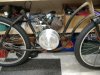
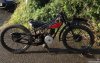
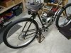
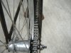
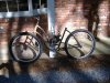
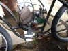
Have been gathering parts for this build for a while. Figured I would work on it while waiting on parts for the Briggs build. So heres a look at the really "rough" rough out. Fabbing motor mounts now.

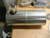
I built a CG using a step thru frame and really like it. The engine is the focal point. This build will be even better with a vintage(c1940) engine. The frame is a 1930s Cleveland Welding unit. They made bikes for many brands.

I say vintage "style" because the rest of the build will use modern components.

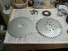
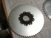
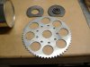
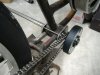
This will be a 3speed IGH, been using these a lot lately, starting with the old Maytag. Drive will be thru the bottom bracket like the Briggs bike. There will be a centrifugal clutch on the jackshaft on right side of the BB driving back to the IGH via a #35 chain(11T/60T). Using the #35 to get the most # of teeth on the smallest sprockets. Starting will theoretically be a pulley in the left side jackshaft next to the sprocket on the BB.

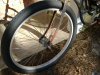
One thing I have never tried is a coaster for the front brake. People have been doing this forever I know but I never have. Have that worked out already.

That's about as far as it is now. This will be a slow thread as the Briggs will soon resume. Will add as it goes along.
 

Attachments

  • Like
Reactions: Nightster

cannonball2

Well-Known Member
Oct 28, 2010
3,682
221
63
Colonial Coast USA.
So while waiting on the slow boat to bring the last of the Briggs parts I got a few things done on this build.

I found a blank 60t #35 sprocket and drilled it to the CG hole pattern. This allows it to bolt directly to an 18t coaster sprocket like used on the 3speed IGH. The 60t 35 is only slightly bigger(looks larger in the pic bit is with in a 1/4") than a 44t CG sprocket.

The main conundrum for this build was getting the jackshaft clutch to engage at a very low rpm. After conferring with a very nice guy-Jim at Maxtorque it was decided that clutch engagement would be in the 1200 rpm range using 62gm heavy shoes and the lightest(yellow) spring. I then set the primary reduction ratio for engine engagement around 2200 rpm. That's as low as I could go and still maintain the overall ratio I wanted.

With the IGH the ratios will range from around 14:1 for first to 7.5:1 for third This gives a top speed of 42mph@ 4000 rpm. Don't really know what the Villiers will max at, but am not really wanting to twist a 76yr old engine very high. I can say right now the ratio over all is probably too high, bit will run it as its what I have.

Also finally got a repro flywheel cover and Villiers enameled badge from England
 

Attachments

  • Like
Reactions: Nightster

silverbear

The Boy Who Never Grew Up
Jul 9, 2009
8,325
670
113
northeastern Minnesota
CB2,
I'm glad to see your build and want to sign up for a seat in the peanut gallery. As you know, I have two slow going builds gathering dust which utilize the Villiars midget 98CC engine. One is a hybrid trike and the other is more like what you are doing using a step through frame from a 1934 Elgin 4 star bicycle. Watching this build evolve will be a treat.
SB
 

cannonball2

Well-Known Member
Oct 28, 2010
3,682
221
63
Colonial Coast USA.
Thanks for the link ElGallo!

What a craftsman! I have made a few items over the years from FG using the foam mold process, but wood? Wow! The tank certainly adds a lot to a step thru frame. Looks really Buck Rogers if you know what that means.

SB I have seen your builds and I congratulate you on the way they are progressing. They will be awesome!
This one will not be so well done but should be fairly cool. Am trying to stay "vintage" for most of the non rolling parts. This is pretty much a prewar age build so am trying to select parts(or style of parts) from that time though some will be later in order to make it function. Like using an SA twist shift which I believe is 50s(you have one I think). Hopefully it will index with the Nexus. I am using a Shimano shifter with the SA hub you sent me on the Maytag. Hopefully it will go the other way.

I believe this is(or similar) where my engine may have started life. It did come with what appear to be lawnmower mounts( half of the set), but I have not seen one in a mower. Maybe I haven't seen the right pic yet. Any way its on two wheels now.
 

Attachments

cannonball2

Well-Known Member
Oct 28, 2010
3,682
221
63
Colonial Coast USA.
Just did a few minor things today.

Drilled lightening holes in the rear sprocket(see the fourth post). Was just for looks making the sprocket not seem so large. But it is noticeably lighter and I wound up with 8 very heavy duty washers in the process.

Also fabbed up a rear mount fuel tank from quart paint cans(new) from Home depot and a few old brass fittings. This one was very easy to make in under an hour. The new cans solder nicely. All cans/fittings were soldered, I just added a bit of JB weld to the neck to smooth the joint nicely.

Got my bearing hangers today. These will have to be used instead of the bolt on flange bearings as the engines sprocket is mounted inboard and the chain line is very close to the bottom bracket.
 

Attachments

  • Like
Reactions: Nightster

cannonball2

Well-Known Member
Oct 28, 2010
3,682
221
63
Colonial Coast USA.
Thanks SB!

Was nice to start with some virgin cans. This tank cost about 6 bucks since I had the fittings. The bean can tank was free but more fussy to deal with. Figured I will jazz this tank up a bit to make it more interesting. May add a sight gauge. Half a gallon is not a bunch of fuel, but its not bad either. Its just the right size to easily fit behind the seat.
 

silverbear

The Boy Who Never Grew Up
Jul 9, 2009
8,325
670
113
northeastern Minnesota
A sight gauge would be nice. I 'll be interested to see how you go about it. I have a stash of sight gauges from OMC outboard motor gas tanks found at the local dump. I must have half a dozen or so. These would be from from Johnson/Evinrude six gallon gas tanks and have as the visible part from outside a glass "bubble" or dome with markings in the glass of full to empty and inside the glass a mobile needle pointing to the fuel level. Inside the tank and hidden from view is an armature with a cork fitted to the end which rides higher or lower with the quantity of fuel. I always wanted to make a tank using one of these gauges, but never did. A bean can did not lend itself to this very well, but your paint cans would. Before soldering the two cans together the gauge could be fitted without having to guess at anything. The armature would need to be shortened and possibly bent at the point it would pass by the filler (dogleg around it), depending on where the filler is located. I think if I ever make another cylindrical tank it will utilize your paint cans and have such a sight gauge. If you want to see a picture of one I'll snap a picture the next time I'm out at the summer place in the woods. And if you want one I'd be happy to send one to you. You've been kind to me in the past and it would be nice to return the favor. That's how things work around here. Anyway, I really do like your tank and think it is a step up from a juice or bean can. Awesome, possum...
SB
 
Last edited:

cannonball2

Well-Known Member
Oct 28, 2010
3,682
221
63
Colonial Coast USA.
That sounds like the same/similar fuel gauges I had in my 1947 Cessna 120. They were in the ends of the tanks in the wing roots. They were somewhat inaccurate but fortunately erred on the-- theres still a good bit of fuel in the tanks when reading empty side. I would love to have a gauge next time you are out that way, that's a very kind offer.

The paint cans are nicer to work with as they are a good bit thicker. Also the cans top where the paint lid seals adds a lot of strength.The trick of working with them is to solder all fittings on first and then drill/ream the holes. The cans wont distort during the drilling like they will with out the fitting in place. I would think the gauges float mechanism would clear the filler neck if the gauge is mounted on the opposite side.

I have a restored long spring Troxel seat for this build hope the tank doesn't hide most of it.
 

cannonball2

Well-Known Member
Oct 28, 2010
3,682
221
63
Colonial Coast USA.
Got a bit further.

Am using the common jackshaft bearing hangers in the BB to get the sprockets as close in as possible. Modded the hangers to use the bolt on method similar to what I used on the Briggs build. This allows easy bearing alignment and a bit of chain tension adjustment. The right side chain line is perfect with the exception of a bit of interference with the upper chain stay. Swapping the thick washer on the axle to the other side should fix that. If not a bit of frame flattening will do it. These old frames are very stout. I can spread most newer frames by hand. Not this one! Will take a scissors jack.

Ignore the junk hardware holding stuff together. Once I get the parts in to establish the other sides chain line it will be time to get back on the Briggs build and shelve this one a while.
 

Attachments

curtisfox

Well-Known Member
Dec 29, 2008
6,046
3,949
113
minesota
KOOOOOOOOOOOL! You should have a chevy exhaust manifold spreader, spreads the frames so easy and nice to use.On more then just bikes................Curt