3+ speed automatic jackshaft idea

GoldenMotor.com

Tony01

Well-Known Member
Nov 28, 2012
1,743
1,749
113
sf bay area
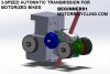
This thread details my thought process, fabrication, assembly, usage, and improvements in making a twin jackshaft automatic transmission for small engines. SEE POST 40 FOR FINAL UPDATE AND SETUP


Got the idea of making a 3-speed jackshaft. Anybody ever had one of those Rupp 2-speeds? I did not, but I had R/C cars with adjustable 2nd gear shift points. They worked well.

The way the 2-speed work is by the use of a freewheel and a cent. clutch inside the 2nd gear. The motor pulls the first gear on the freewheel, and then when the jackshaft spins fast enough, the 2nd gear engages and spins the JS faster than first gear, which makes first gear freewheel.

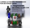
RC car company Kyosho made a 3-speed for their Mad Force. They combined the cam from 2nd gear and the FW from first gear, to make a middle gear. Thus, after the 2nd gear cam engages, it drives the JS faster than 1st making it freewheel, but not fast enough for 3rd to engage. As the JS spins up even faster, 3rd gear engages and forces 2nd to freewheel on the shaft.

This could be adapted to motorized bikes. I would put all the driving gears on the crankshaft but there might not be enough room.

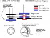
Picture shows two cam ideas. Second one is adjustable with a set screw and spring weight. Using more than one middle gear of this type could give you an overall 4- or 5- speed transmission.. it would be heavy though.

Of course, you'd only get engine braking in top gear.

Thoughts? Would you buy one?
 

Attachments

Last edited:

Tony01

Well-Known Member
Nov 28, 2012
1,743
1,749
113
sf bay area
Now I have.. that is a good setup. Something like that, but instead of MT gearshift clutches use cams. The lockup would be far more solid and 100% adjustable. Although.. every gear change would put great strain on the system. I need to research it some more. Some RC cars use the shoe type clutches for gearshift as well, there must be a reason for that.

One problem would be the cost to machine the cam parts. I already have the design and machining process in my head - you could do everything on a manual lathe and manual mill. Probably machine the finger slot first, then flip it over and locate on that and drill the threaded hole for shift adjustment. So we're talking:

Cams:
OP 1, 2 lathe OD turn and bore for bearing press fit.. +/- .0005" cut soft jaws for op2
OP 2, mill finger slot.. carbide tools only..
OP 3, drill/tap adjustment
OP 4 drill finger pivot. press fit pin. reamer +/-.0002"
deburring

Cam outer:
OP 1,2 lathe bore for bushing press fit also tight tolerance, cut soft jaws for op2..
OP 3 drill finger catch pin hole, press fit pin, 1/8 reamer..
deburring

A machine shop running at $100 per hour would take at least 3 hours to make a prototype, we'd need two such cams for a 3-speed so maybe 3 or 4hrs, that is $300 or $400. not mention material orders, saw cutting, inspection.

Another problem is doing all this work and then finding it doesn't work properly, like the gearshift is "too rough" and/or puts too much strain on the engine. In which a belt drive from engine might be good, but how much it might help is not clear.


The next time I have access to a machine shop, be it working in one or working as an engineer in a company with one, I'll get started on it. I need to update my Solidworks to the latest free student version.. will make a drawing for you guys to see.
 

GearNut

Active Member
Aug 19, 2009
5,104
11
38
San Diego, Kaliforgnia
Well, I do have a small hobby lathe, drill press, and am very handy with a dremel and files.
I wish I had a mill. The hobby mills are just too expensive for me right now.
 

bowljoman

New Member
Aug 7, 2010
370
1
0
Wa
LR jerry, your auto shifter is the way to go for sure automatic. This tranny is not automatic. It requires a cable to be pulled for 2nd gear. You may be able to get the one-way bearings and belts as replacements. It utilizes two clutch plates between the gears. pull the cable and the 2nd gear roller is forced against the first gear roller. and the first gear has the one-way bearing. I bet you could use two BMX freewheels... the ones they sell for pocket bikes and screw on whatever you want to drive them.
 

Tony01

Well-Known Member
Nov 28, 2012
1,743
1,749
113
sf bay area
So when 2nd gear is engaged, is it also freewheeling? What I mean is, do you get to use engine braking in 2nd gear?

I'm exploring options for shifting. Looking at honda dirtbike semi-auto transmissions. They have a total shift ratio of something like 3.5 using a slight overdrive in 4th gear.

Would be awesome to run an auto clutch with paddle shifters. My 3-speed idea is full mechanical and only gives the engine braking in top gear. I would prefer to have a non-freewheeling transmission with semi-auto or auto shifting.

The simplest solution would be to install a bigger motor and keep the CVT... But there's just something about the smaller CA-legal flathead in there.
 

GearNut

Active Member
Aug 19, 2009
5,104
11
38
San Diego, Kaliforgnia
Just remember, with the new laws here in Cali. the engine is limited to < 4hp. We now can go above the old < 2hp! I am now looking at the HF 79cc, but they are not available in Cali. :( (think Yuma, AZ ;) )
 

scotto-

Custom 4-Stroke Bike Builder
Jun 3, 2010
6,505
24
38
Ridin' inSane Diego, CA.
Just remember, with the new laws here in Cali. the engine is limited to < 4hp. We now can go above the old < 2hp! I am now looking at the HF 79cc, but they are not available in Cali. :( (think Yuma, AZ ;) )
Dan, you can buy them here in Cali., they just ship them to you. They don't have them in the stores here but they will ship to you......ask me how I know ;)

Why drive to Yuma when you don't have too?
 

Tony01

Well-Known Member
Nov 28, 2012
1,743
1,749
113
sf bay area
GearNut, after a few days of thinking how to adapt multi speeds to my bike, I've come to the conclusion that it's possible. My fabrication capacity is limited practically to zero- vice, hand drill, and hacksaw - but it's possible to adapt at least a two speed to the setup I have now without moving the final drive sprocket.

I can put another JS on the other side of the seat tube, on the same mounts that JS1 is on now. There is barely enough room between motor and seat tube to fit a shaft with small drive sprockets.

Due to the width of the PB bearings and the seat tube JS mounts there appears to not be enough space for a 3-speed. But for a 2speed, it's just enough. The sprag sprocket will go on the engine side, and the 2nd gear can will go on the other side near the pedal freewheel.

Or, I could turn my JS mounts 90deg around on the seat tube and fabricate some plate mounts to fit four plate mount bearings. They would likely have a smaller width than the PB bearings and would be stronger as a whole.

Adding a 3rd speed would be a simple matter of space available, and fabrication of just one part- a cent. clutch riding on a sprag needle bearing rather than a simple bushing.


In the pic, I'm talking about that space right there, between the engine and JS mounts. Not a whole lotta room.


An one more thing- it might be difficult to find a sprag 1st gear sprocket... But I've seen those large sprocket freewheels that mount to FW threads. Could use a staton adapter like I have for my pedals, or somehow find a bearing for 5/8" shaft with an internal keyway and some sort of external keyway or mount setup.

Only one cent clutch needs to have the shoes spun by the engine- the 2nd gear could be spun by the shaft thus engaging a clutch bell driven by the 2nd gear sprocket.
 

Attachments

Tony01

Well-Known Member
Nov 28, 2012
1,743
1,749
113
sf bay area
And a thought about using the four holes around the crankshaft to add another plate for strength, but there just isn't enough crankshaft length to be able to put the cent clutch with sprocket inboard. I could do sprocket outboard, but it's unnecessary strain on both engine and js bearings... And I would not be able to tighten the clutch set screw with the sort end of an Allen wrench.