My latest B&S bike

GoldenMotor.com

msrfan

Well-Known Member
Sep 17, 2010
1,808
120
63
Southern California
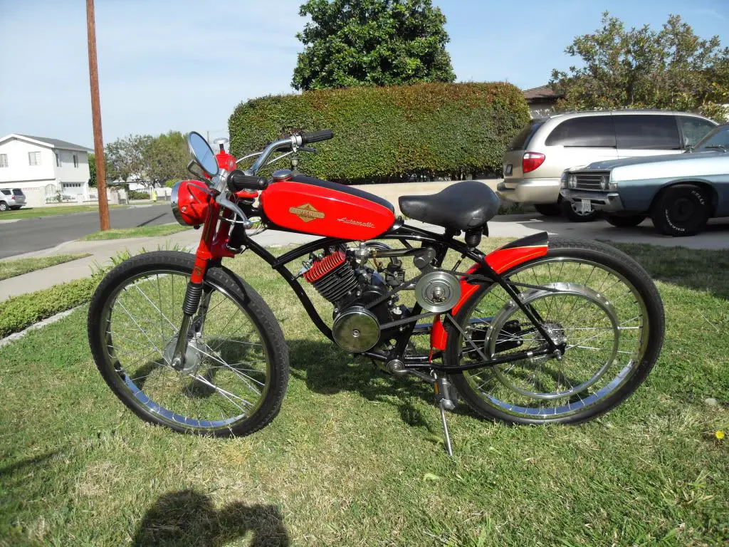
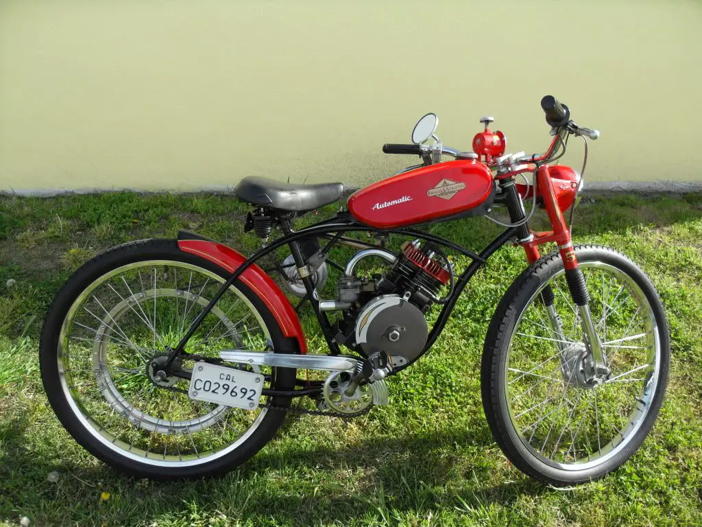
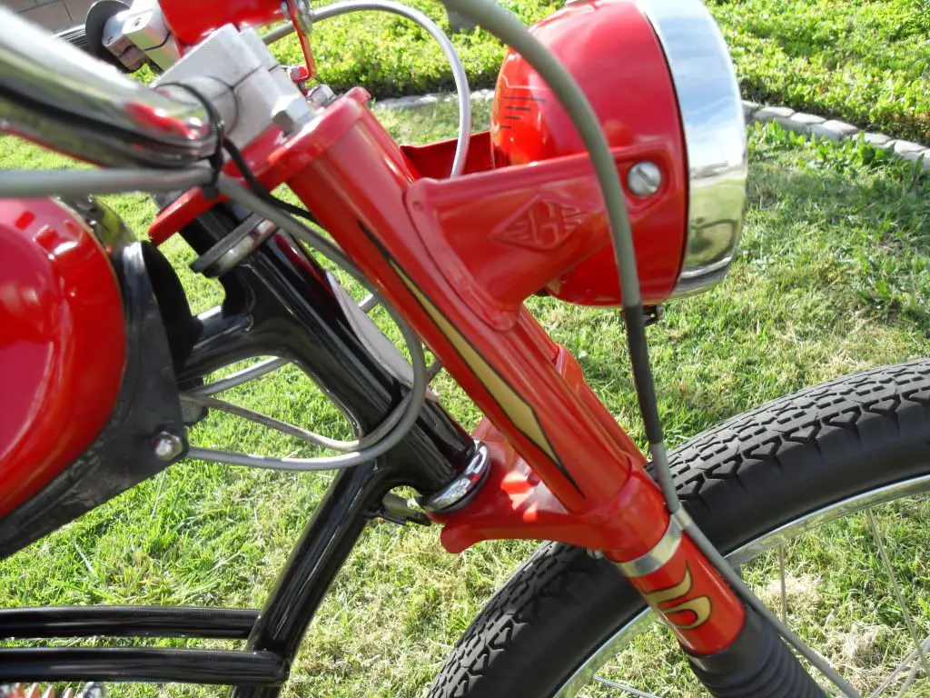
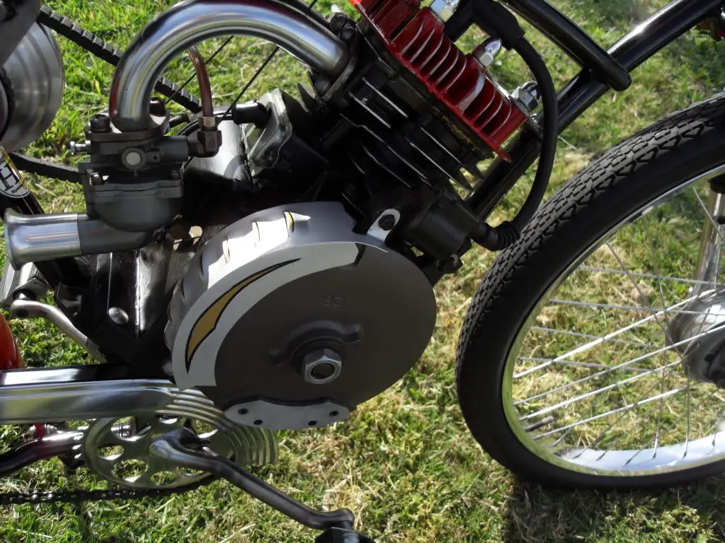
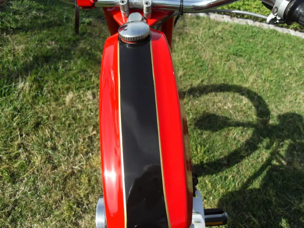
My friend, Dan, and I built this one about 4 years ago for him. This has all my latest ideas in one bike. Engine mounted Motobecane variator clutch, LED headlight and tailight with stoplight. Battery pack with charging system, weighted flywheel to make up for what we removed, all with his bobber look. A little port cleanup and it runs real strong. We had a heck of a time with the clutch. First we cut off the shaft holding the clutch and grafted it into a Briggs 5hp. The variator has three circuits. Starting shoes that fly out inside a drum when pedalling that starts turning the motor. We had to add 1/4" plates to those to make them heavy enough because moped motors turn at higher rpms. More shoes mounted onto the outside rim of that drum spring loaded to fly out in another drum that turns the wheels when the motor starts. We had to slot the springs so they would fly out easier. And finally steel balls on a ramp that squeezes the pulley halves together giving cvt ratios. Dan machined a new plastic part that holds twice the balls. It worked at last performs great. Batavus fuel tank, moped front drum break-forks-headlight-controls, and Honda ingnition coil. Now for the charging system. I had a brainstorm about using a Sturmey Archer Dynohub, so that's what we did. Dan machined a solid aluminum billet double pulley to accept the little alternator and 2 large bearings. Bulletproof. Riding on a hollow axle allows the wires to reach the frame nicely. Mounted on a double pivoting spring return bracket lets the whole mess swing forward and down when the front pulley closes, keeping consistent tension on both belts. Okay, the Dybohub puts out 6 volts when laced into a front wheel. Spinning it at motor speeds produces around 87 volts. After months of trying to figure out a rectifier-regulator I was walking down a row at the Golden West College swap meet and spotted a box full of charging modules for cell phones, etc. They're all 120 volts ac input, and the output varies but is always dc. So, with a little experimenting we put together a small battery pack, installed it into the headlight bucket and it's been keeping it charged perfectly. What a stroke of luck. There's an on-off switch hidden under the seat with the charging module. A small front sprocket to clear the engine and ease starting. It uses my standard internal compression release. Dan's had this bike up to 50mph on PCH, but it's just at home putting the neighborhood. The 5 on the forks stand for the fifth B&S bike build using my basic design. Got two more in the works. I will post as I go. Thanks for checking out my stuff. I love all the bikes I've seen on this forum.


timboellner

Member
Apr 1, 2009
435
0
16
Towson Maryland
I thought your last B&S bike you posted was awesome.
I made it my desktop background for the last 2 weeks.
Again, good job man.
That's one pretty bike.
I guess you gave me this weeks new background .
Still wish we were neighbors.

TIM
 

silverbear

The Boy Who Never Grew Up
Jul 9, 2009
8,325
670
113
northeastern Minnesota
A lot of nice details on that bike. Another inspiration! I see that is a Hercules front fork. I have one just like it. Your little book is one of my treasures, getting thumb worn.
SB
 

chainmaker

Well-Known Member
Jan 19, 2010
2,634
69
48
Ma USA
This bike is Awesome!!!! I like everything about it. Where are you hiding the battery pack ? My next bike is going to be a Briggs , so Ive been reading your posts..Fine work !!

Edit... just re-read the post and found it !
Cheers
 
Last edited:

silverbear

The Boy Who Never Grew Up
Jul 9, 2009
8,325
670
113
northeastern Minnesota
This thread deserves to be bumped anyway so that more people can see what can be made from scratch... I'd rather have this bike of yours than a Whizzer any day. It is CUSTOM and one of a kind.

I have a couple of questions to bother you with. I posted a note to Harry76 this morning hoping to get a link to the great info you gave on attaching a sheave...

"Harry,
Maybe you can help me find it. I thought this was on your thread, but if it is I just missed it again. Msrfan was showing another means of attaching the sheave to the rear wheel by means of some little dealies that he adapted to snug the sheave rim directly to the spokes. Not the commercial ones for Whizzer, but something else. I'm thinking that I might be able to avoid altering the frame to make adequate clearance for the belt by getting it in as close as possible to the wheel, using a narrow wheel rim for the sheave in the first place and lining up the belt pulley with the jack shaft. I hope.
I should have saved his commentary and photos when I could have. Now can't find them. Thanks,
SB"

I have just spent the last hour and a half looking... no luck. So I will ask my teacher to explain again or tell me where to look so you don't have to. This is in reference to the Indian tri-car build on the Indian Tadpole thread. I'm at the mocking up stage yet, about to make the engine mount ears for the Villiars engine and intend to make up a jack shaft arrangement much like Harry76's on his Villiars Beach Cruiser build. If I can avoid a dogleg in the frame I'd rather, so my thought is to tuck the belt in as close to the frame as possible.

My second question has to do with the tool you made for crimping the frame where the belt wants to come in contact with the Schwinn frame on your Briggs builds. (I don't know if it will also on my Worksman frame, but figure the chances are good it will.d)Could you, would you (please, please, please) give some photos and commentary on how you made this tool?

There are going to be more builds done by others using belt drive and older motors like the Brigs and the Villiars, so it isn't just me who will benefit from your knowledge. And at some point we need to put all of it together... the alternate means of attaching the sheave... giving clearance... into one sticky easy to find for tomorrow's builder. I will volunteer for putting it all together in a central thread later on and will give credit where credit is due, but if you could help out now with your approach it would be much appreciated.
SB
 

msrfan

Well-Known Member
Sep 17, 2010
1,808
120
63
Southern California
Okay sb. It's pretty basic. I started with a couple chunks of steel welded together and added more pieces in the shape of the crimp I wanted. Then drilled and tapped holes to mount automotive studs to it. After that I formed a female piece from a piece of aluminum to cradle the frame. I went with sizes to fit most frames but mainly Schwinn tubes. One large for the lower tube and a smaller for the top. Some manifold heavy washers and fine thread coupling nuts finished it. Later I added another strap of metal to keep the tool from twisting while tightening. The hardware came from the automotive industry. Napa is a good supplier. If the tubing you're crimping fits loosely. you can shim it up with anything handy, like leather, cardbaord, beer cans, etc. It's not the best looking crimp because it still seems to distort the outside of the tubing a little, but it's miles ahead of the hammer and chisel method I've seen on some. The better you make the tool and use it, the better your frame will look. You can see the results on pacesetter's Roadmaster in his thread. Good luck and let me know if you need more info.


silverbear

The Boy Who Never Grew Up
Jul 9, 2009
8,325
670
113
northeastern Minnesota
Okay sb. It's pretty basic. I started with a couple chunks of steel welded together and added more pieces in the shape of the crimp I wanted. Then drilled and tapped holes to mount automotive studs to it. After that I formed a female piece from a piece of aluminum to cradle the frame. I went with sizes to fit most frames but mainly Schwinn tubes. One large for the lower tube and a smaller for the top. Some manifold heavy washers and fine thread coupling nuts finished it. Later I added another strap of metal to keep the tool from twisting while tightening. The hardware came from the automotive industry. Napa is a good supplier. If the tubing you're crimping fits loosely. you can shim it up with anything handy, like leather, cardbaord, beer cans, etc. It's not the best looking crimp because it still seems to distort the outside of the tubing a little, but it's miles ahead of the hammer and chisel method I've seen on some. The better you make the tool and use it, the better your frame will look. You can see the results on pacesetter's Roadmaster in his thread. Good luck and let me know if you need more info.


Perfect. I think this will do it. Thank you so much. When the dust settles at some point I promise to pull all of this together in a thread on sheaves and belt drives that may become a sticky if it is useful enough.
SB
 

msrfan

Well-Known Member
Sep 17, 2010
1,808
120
63
Southern California
Your an ideas man MSRFAN. Love that crimping tool
Thanks, Harry, I used to have guy crimp my frames that I was using for Whizzers. The depression it made was teardrop shaped and was perfect. With the different size pulleys you guys are using, the Whizzer location for the crimp would be in the wrong place. Anyway, with a little metal work they look great.
 

curtisfox

Well-Known Member
Dec 29, 2008
6,046
3,949
113
minesota
Perfect. I think this will do it. Thank you so much. When the dust settles at some point I promise to pull all of this together in a thread on sheaves and belt drives that may become a sticky if it is useful enough.
SB
What a awesome simple tool. Thanks for shareing........Curt