briggs kick start motorbike

GoldenMotor.com

MEASURE TWICE

Well-Known Member
Jul 13, 2010
2,742
1,214
113
CA
I would think the crank would hit the oil if tilted too far
================

FROM: MEASURE TWICE

AFTER THOUGHT, AND OTHER FIXES FOR CARB.....

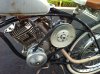
I was thinking about this and Corgi1 had must have thought what may actually be happening if tilted far forward, like looks like 45 degrees.

The counter weight on the crankshaft although not extending as far as the splash fork connected to the bolts at the bottom of the connecting rod, would probably be splashing oil that was in the sump.

This type of arrangement is an oil sump moved to from the bottom of the crankcase, to basically half on the bottom of the crankcase and half on the front of the crankcase.

Anyone with x-ray vision care to tell us for sure what is happening?

Only thing that would show up being a problem that I could think of now is too much oil, not just splash on the bottom of the piston to cylinder wall, for the oil scraper ring to deal with. Then a smoky exhaust would have happened, which I guess it had not got to that extent and works OK, so it does not matter.

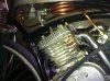
With my 22.5 degree forward tilt on the engine on my frame, I thought that I would have a little higher up oil level in the sump in the crankcase aft. This is getting close to the camshaft and valve tappets and oil breather. The oil breather choking with oil would be bad, as it is just for venting pressure in the crankcase and sending oil vapor back to the carburetor to burn along with fresh air fuel mixture. What I did notice is that the oil breather uses a channel that has a guard in the crankcase to prevent oil from splashing in it. It is the curved metal portion that the oil vapor pressure has to snake up and around before it ends up where the bottom of the valves are. The oil vapor plays a novel idea besides venting oil vapor pressure, helps lubricate the bottom of the valves where the springs are, that is neat.

I did see somewhere about some guy taking two Briggs Vertical Shaft lawn mower engines, each somewhere in the 3 to 5 hp range each as I best can recall, and make a single engine with one head if you please. The 1 spark plug with both piston heads timed to compress simultaneously. Too bad he did not have auto compression release to help start the thing. But I bring this up because at the time the guy mentions that he had not gotten a way for the oil to be used in the crankcase and instead used a lot of grease and ran only for short periods. Another reason, and I not sure why he could not fabricate for the trial run with a better than high temp RTV for the head gasket, but that was another reason he had to limit the run time. Maybe you all have seen the video on Youtube.

Something maybe of use on to someone that had to find a way of removing a cylindrical main fuel nozzle in the bowl of a carburetor is this. I was following the instructions manual on this outboard motor on which way to put the cylindrical main fuel nozzle back in once I cleaned it with compressed air.
I had not noticed the very slight difference in diameter of the ends of the cylindrical main fuel nozzle and referred to the manual.
I could have if I’d known had the carburetor inverted so that when I unscrewed the main jet, the cylindrical main fuel nozzle would not have fallen out, with me no seeing which way it fell out. At least I had the forethought to get a cookie sheet with rimed edges to catch parts that fall out during disassembly and not roll off a table into the lawn to try and use a metal detector to find later.
The thing with this Honda manual is what I may get to contacting them about, but if I had looked over the whole page carefully, I would have noticed that the inset for the direction of the cylindrical main fuel nozzle was carefully shown in the correct direction with an arrow. That is correct in the inset, but just the opposite in the smaller exploded view. I have the thought of scanning the drawing of the part in the exploded view, printing it out, the covering the wrong view of it in the manual by pasting it back in the page over it correctly.
The cylindrical main fuel nozzle got jammed in when I tried to put the main fuel jet screw in on top of it, but the threads would not engage. When I realized that there were two sets of threads and one was larger than the other, I had then known that the cylindrical main fuel nozzle was not going in far enough. Then I figured I would remove it and see if I could see find out what was the problem. I picked out one of those large curved sewing needles that are used to sew shoes with. I put the pointed end inside the end of the cylindrical main fuel nozzle. I then put sideways tension on the needle and tried to twist and pull the cylindrical main fuel nozzle out. When this did not work, I was about to give up, but got the idea to use the eye of the large curved sewing needle in the end of the cylindrical main fuel nozzle. Then I found that the two metal sides of the eye of the needle were compressing slightly when inside the end of the cylindrical main fuel nozzle. It enabled me to pull and twist the cylindrical main fuel nozzle out. Once out I held the nozzle in one hand and pulled the eye of the needle out. Only for a few very small scrapes on the inside of the nozzle nothing was damaged. The holes in the side of the nozzle left undamaged and I noticed that I could now put the cylindrical main fuel nozzle back in with the smaller diameter end so that it seated all the way down properly. The threads worked and finally with float and needle valve and gasket back in place I put the bowl back on with the washer and fuel drain and it’s threads worked OK too. The only problem after that was getting all the areas of the fuel tank, lines, bowl, jets, and nozzles all primed and the engine worked fine after a long time of one and a half years drained of all fuel in tank and carburetor.
Tools, you can’t have too many of them, and knowing how to improvise with them, indispensable!

PS the idea came to me today. Sometime with a twist on what Whizzer uses.
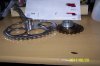
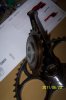
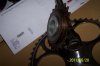
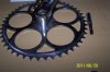
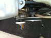
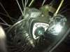
I HAVE AN IDEA FOR THE PULLEY ATTACHMENT SHIM PROBLEM ON MY REAR WHEEL FOR V-BELT DRIVE. I am going to go out looking for small U-bolts, or made parts myself to grab points where spokes cross one another and attach to the wood sandwich and washing machine pulley. Then I have almost to the point of trial run ready to go!.spr.

Aint the smiles on this site great, I just found Smiles(More) and this looks like me with the hub problem;)
MEASURE TWICE
 
Last edited:

briggsbiker

New Member
Nov 18, 2010
65
0
0
33
Riverside, CA
I have a question for briggsbiker. I am looking into trying to make my bike build using a briggs and stratton with a kick start like yours.

My question is, does that gear that is attached to the flywheel screw on to the existing shaft, or is it held on by the bolt that I see in your pics?

I have been having a hard time locating a briggs kick start assembly, so I bought a maytag washer engine kick assembly instead. The gear that would go onto the flywheel shaft is too large to thread onto the shaft. I am just trying to brainstorm ideas of how to get this gear attached to and working on a briggs engine.

Thanks for any help you might be able to give me,

Gilbert
Sorry i have took so long to respond, i have been pretty busy with work so i had to put my bike on a hold for a while. Yeah i almost bought a whole engine also just for the kick start becauuse the assemblies dont come around very often. I finally got a chance to get you some close up pics of the gear attacked to the shaft. In order for the gear to fit over the shaft, i had to file down the threads on the shaft enough to put a piece of pipe in between the gear and the shaft. that will fill the gap and hold the gear snug on the shaft. Then i drilled and tapped the center of the shaft for a 5/16" bolt to hold the gear on. Then i drilled and hammered in 1/8" roll pins in the flywheel between all the gears. This will lock the gear in place and hold it on solid. I will get back to you on the clutch adjustment as soon as i can, i will take some close up pics for you!
 

Attachments

Gbrebes

Well-Known Member
Jul 16, 2010
656
260
63
Los angeles
Thanks a lot Briggsbiker, I really appreciate the help and pictures. I am fairly mechanically inclined, but I do need help with details such as roll pins to hold a gear in place and double pulley tension adjustment mechanisms. I have never really done anything like this before and its amazing to me that I can learn about it on a website on my computer and then go out to the shed and fabricate something that I really could not do all on my own.

Thanks a lot and looking foward to more pics,

Gilbert
 

NEAT TIMES

New Member
May 28, 2008
1,964
1
0
PENSACOLA, FL
A Staton freewheel adapter could be easily mod`ed to attach to the fly-wheel for making a kick start using a short chain with a freewheel sprocket and maybe a salvaged cycle kick arm.

Just thought I would toss the idea out here, never thought about it until tonite reading this thread .

Ron
 

silverbear

The Boy Who Never Grew Up
Jul 9, 2009
8,325
670
113
northeastern Minnesota
A Staton freewheel adapter could be easily mod`ed to attach to the fly-wheel for making a kick start using a short chain with a freewheel sprocket and maybe a salvaged cycle kick arm.

Just thought I would toss the idea out here, never thought about it until tonite reading this thread .

Ron
Explain that a little more if you will, Ron. I don't even know what staton free wheel is or looks like. How would it attach to the flywheel? And how does the chain part come in to this? I think a lot of us would like to come up with a kick start if we knew how.
SB
 

harry76

Well-Known Member
Apr 16, 2011
2,557
47
48
Brisbane, Australia
Is that a front disc brake? If so what brand is it and how does it perform?

If it performs ok it seems like a perfect choice as it still seems to "fit" in with a vintage build. Very very nice bike by the way
 

NEAT TIMES

New Member
May 28, 2008
1,964
1
0
PENSACOLA, FL
Sb

briggsbiker did a great job of fitting the motor in the frame and all the other details. A motor machine to be desired, no doubt about that!

Hoping this freewheel kick start idea is ok to post in his thread.

May need more coffee to get my heart pumping, am a slow starter in the mornings.

The "staton" freewheel adapter ($15) and a freewheel sprocket would add 1/2" width to the flywheel. The adapters have different bore size`s. The od is the same on all, they are od threaded 1&3/8" 24tpi for freewheel sprockets and freewheel hubs for larger sprockets.

A 1/2" long piece of shaft could be drill and tapped with threads to screw on the crankshaft threads. (weld drilled and threaded 1/2" long piece of shaft inside the freewheel adapter). A spring return chain could be fashioned to a kick arm of sort.

The "staton" freewheel adapter`s have keyed bore size`s from 5/8" to 1". therefore a piece of keyed shaft could be used and held together with a crank shaft bolt and washer, (not welded) it that option is available.

While "pondering" , the thought of a rack gear (eliminating the chain) mite be made with sections of large pedal sprockets welded together for tooth width and engage the freewheel crankshaft sprocket. The freewheel sprockets are tuff, hardened steel.

The large laminated chain ring sprocket sections may allow the radius needed for a pivot shaft mount. Now= a donor bottom bracket mite be used for a shaft mount and a modified pedal crank for the kicker.

As stated, this is a concept developing as I text. Who know`s, it could be accomplished !! LOL.

I can do a sketch etc if anyone desires it.

Ron whew! refill time!! ________cvlt1
 

silverbear

The Boy Who Never Grew Up
Jul 9, 2009
8,325
670
113
northeastern Minnesota
Ron,
I don't want to high jack this thread into a different direction, but I know others would love a kick start, too. Part of what is so eniviable in this build is the kick start. I'd love to see your concept built by someone or at the least a drawing or two. If it isn't OK to post it here, maybe you could do a new thread. I know there will be interest.
SB
 

briggsbiker

New Member
Nov 18, 2010
65
0
0
33
Riverside, CA
Thanks for the comments! I like the ideas here, it took me some time to come up with how I was going to put a kick start on mine! Keep the ideas coming!
 

briggsbiker

New Member
Nov 18, 2010
65
0
0
33
Riverside, CA
Is that a front disc brake? If so what brand is it and how does it perform?

If it performs ok it seems like a perfect choice as it still seems to "fit" in with a vintage build. Very very nice bike by the way
Thanks! Yeah it's a shimono disk brake! It performs well but not as well as the new disk brake systems. When I bought the bicycle at the swapmeet, it had the disk brake setup already, haven't seen any other one like it!
 

harry76

Well-Known Member
Apr 16, 2011
2,557
47
48
Brisbane, Australia
Dont go selling it then... unless you wanna sell it to me? LOL. Really suits your build. Absolutely love it. Love to see more pics of this bike if possible. Cheers!!!
 

NEAT TIMES

New Member
May 28, 2008
1,964
1
0
PENSACOLA, FL
WITH BRIGGSBIKER`S BLESSING;

Attaching some pic`s for diy kick starter idea`s. The chain ring and pedal crank are for idea`s only, they were handy for pics. Would use a straight pedal crank and maybe a non-dished chainring for laminating for wider teeth on the kick pedal part, or possibly a guide on each side of the chainring teeth.

The sprockets could stay engaged or just use section`s of large chain ring and let pedal rest in the kicked dn position.

The sprockets in these picture`s have a 5.5" center to center distance.

In my experience most fly wheels fit a taper with a keyway`s and a key, then held in position with a nut.

The adapter pictured has a 7/8" keyed hole. A 1/2" length of keyed or non-keyed 7/8" shaft could be accurately center drilled and tapped to match the motor thread. Weld the shaft into the adapter. (staton sells the same adapters with 3 groves for a optional mounting of a thin sprocket with the freewheel for jackshafts) I would opt for the grooved adapter .

The complete free wheel assembly with adapter and threaded shaft section only add`s 1/2" to motor width. Maybe less than the factory nut. Note; needs to be right hand thread.

The freewheel sprocket will screw on from both sides, but only one side will be correct for kick starting. Flip it over for driving a wheel = but then it will screw off the crankshaft unless pegged some how.

This is much easier than i thought at first.

Ron
 

Attachments

Last edited:

briggsbiker

New Member
Nov 18, 2010
65
0
0
33
Riverside, CA
Dont go selling it then... unless you wanna sell it to me? LOL. Really suits your build. Absolutely love it. Love to see more pics of this bike if possible. Cheers!!!
Oh I don't think I would ever sell anything off my bike haha I'll keep it for as long as it lasts! I will definately post more current pics for you guys tonight!
 

briggsbiker

New Member
Nov 18, 2010
65
0
0
33
Riverside, CA
Thanks for the ideas Neat Times! I saw some old engines that used a chain and kick pedal system. I also saw a board tracker motor bike that used the pedals from the crank and attached the chain to the engine. Both pedals are in the forward position, then when kicked down it turns motor and springs back up.