Performance CDI layout and schematic diagrams

GoldenMotor.com

KCvale

Well-Known Member
Feb 28, 2010
3,966
57
48
Phoenix,AZ
KC, the problem switches is that with the slightest is vibration you lose contact which in turn will cause a erotical performance and possible engine damage. It's been tried before.
Well that is just silly, I use all kinds of switches on my motorized bicycles and many other things and they all work as intended, if the 'slightest vibration makes them fail' is the problem you have then either your bike vibrates like an unbalanced blender or you are using Wallmart quality switches.

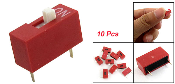
I use quality switches be it toggle, DIP or Keylock and after 30 years of dinking with little PC Motherboard jumpers I'll use DIP switches like this, 10 for $6, when I build mine.


I am regretting throwing out all of my PC board making equipment (except the drill press, tiny drill bits and black light) when I moved as I had everything for photo-etching PCB's and made over 100 little devices from my own PC design to finished product.

It's not cheap to get started nor easy to do, and it's messy, especially the etching solvent as it is designed to eat copper so it eats everything it touches.

Not worth it for the hobbyist to make one item but well worth it if you want to build 50 or more a year of something as you can lay out several on a sheet of copper covered PCB and etc a few all at once and cut them out and drill 'em.
 
Last edited:

KCvale

Well-Known Member
Feb 28, 2010
3,966
57
48
Phoenix,AZ
Hi KCVale, thank you very much for that, much, much better. Ur question about the miniature pots fits in perfectly with the next step I was meaning to describe.
You are welcome for the pic hosting and you can use them anywhere, I don't care about direct pic linking for things like this.

Keeping with the idea of a sealed CDI box it has to have external adjusters as things change, from just adding an X-chamber to new Mag coil or magnet to a whole new engine you want to be able to keep using it and just make adjustments for the changes.
By the way, nice job on the key lock ignition there KCVale, nice looking bike also, wot we can see of.
Thanks, that is a pretty old build, at least 3 years ago as the pics were taken when I first moved into the new place and the shop carpet was brand new.


The carpet looks nothing like that now hehehe ;-}
The 3 position switch for the timing caps isnt a bad idea either, for a daily ride type aplication.
Cheers
I thought about a variable cap for that too but they are pretty unreliable and hard to find so just a rotary switch or a couple of DIP's would be better and again something you could adjust externally of an enclosure.

What coil are you using?
 

KCvale

Well-Known Member
Feb 28, 2010
3,966
57
48
Phoenix,AZ
Now if you'll excuse me I have to make another pitcher of margaritas !! Switch it Bro ham !!!! LMAO laff
Frothy with salt on rim for mine ;-}
Ever had Mescal Margareta's?
Back in the days I played in Nogals I'd bring home a local Mescal called Piramede for 'rita's, simple mixing instructions.

Fill blender with ice.
Plop in a little 8oz can of frozen limeaide.
Fill remaining blender room with mescal including the worm (about 1/2 a bottle).
Mix a little and get a very different alcohol high.
Don't forget the salt and lime ;-}

Note, the US mescal is a joke at like $30 a 1/5th so don't bother but that local stuff at like $5 was outstanding.
 

ivan H

Member
Oct 8, 2011
622
1
16
australia
Hi KCVale, thats is a nice looking bike. I think the switches would be ok, especially the little slider type that u show above. I cant see them failling. In amps I use mini toggles to control relays (with footswitch over ride), or mini DPDT or TPDT toggles for signal routing, & use just normal trim pots for like bias voltage adjustment & have no problems with vibration. When u think of an amp head sitting on top of a 4 x 12 inch speaker cab belting out in the viscinity of 120 decibels for hours at a time they are being subjected to a fair bit of vibration without a problem. It wouldnt be hard to damp a lot of the vibration when mounting a CDI to ur frame.
I also considered using a variable cap (trimmer cap) but tend to agree that there'd be reliability issues.
Putting together small things like CDI's to sell isnt really my trip,,, now valve (tube) guitar amps, thats a different story.
With regards to the 2 pix u helped with, I dont know how to move them or link them anywhere, there fine where u've put them. I do appreciate, very much.
Well, its 11am,,, gotta be margarita time. Cheers
 
Last edited:

Thud

New Member
May 26, 2010
205
0
0
West Michigan
Just popping in to say thanks for the clear drawing of the circit.
It will be a good "deep winter" project for me.

Any one here ever used the laser printer/iron transfer proccess for prototyping pc boards?
I just did a run of pcb's to hold some hall sensors on an e- project. Simple to do & radio shack has the ferric chloride on the shelf.....drilling the holes is the hard part. (Thank you mighty Dremel drill press)
 
Last edited:

KCvale

Well-Known Member
Feb 28, 2010
3,966
57
48
Phoenix,AZ
Hi KCVale,
With regards to the 2 pix u helped with, I dont know how to move them or link them anywhere, there fine where u've put them. I do appreciate, very much.
Well, its 11am,,, gotta be margarita time. Cheers
Just right click the pic and click 'Copy Image Link', then you can paste it anywhere you want as it is a direct link to the image on my server.
 

KCvale

Well-Known Member
Feb 28, 2010
3,966
57
48
Phoenix,AZ
Any one here ever used the laser printer/iron transfer proccess for prototyping pc boards?
I just did a run of pcb's to hold some hall sensors on an e- project. Simple to do & radio shack has the ferric chloride on the shelf.....drilling the holes is the hard part. (Thank you mighty Dremel drill press)
Never tried the iron-on transfer thing, I used photo sensitive copper boards and printed my schematic on a clear plastic sheet, put the sheet on the board under a black light, then dropped the board in the etching solution.

Everything that was not covered by the schematic printing gets etched away.
That being the case you have to be very careful with the board once you take it out of the black bag as even sunlight will activate the photo-sensitive solution and it's copper will be etched away.

Be very wary of that ferric chloride solution, that stuff is nasty and will eat most anything except glass and some plastics.

I don't have a dremmel, I have a drill press with a 1/4" drill that will hold the tiny drill bits but regardless a drill press of any kind sure makes short work of drilling all the component lead holes.

Though you could just use a black Sharpie on a piece of thin clear plastic like those 8 1/2x11" notebook plastic cover sheets to draw your schematic on there are (or at least were) pretty cool free computer programs with all kinds of pre-made part templates which for things like IC chips, transistors, relays, etc made the job a whole lot easier so check into that if plan to make boards.
 

ivan H

Member
Oct 8, 2011
622
1
16
australia
Hi HD, great idea using 3 jumper pins in each position instead of 2, so that when the component is taken out of circuit the female (jumper shunt) is still attached to the board. If everyone contributes their ideas we can really refine this sucker. Great to hear that on ur first attempt it outperforms ur Jag CDI. Well done. Cheers
 

ivan H

Member
Oct 8, 2011
622
1
16
australia
Man, dont think about it, just get in & do it. U wont regret it. I've been building them & using them for a couple of years without a problem. Mine has at least a couple thousand kilometers on it (& thats probably underestimated) & still going as good as day 1. None of the others I've built for friends have had a problem either. It just took so long to get a layout up due to me not knowing how to use a computer. Order the components (or buy over the counter), follow the instructions given & use the layout & it'll work. Dont hesitate to ask if ur not sure of anything (b4 u put it together) & we'll get u sorted. The more positive feedback we get, the more people will build them. If u dont already have a small MX coil to use get a CR80 coil off ebay as they are cheap & give a really hot spark.
Read Huffydavidson's last post just a few post's back, there's all the reason u need right there to do it. Cheers
 
Last edited:

ivan H

Member
Oct 8, 2011
622
1
16
australia
Hi KCVale, pretty much any coil off a Moto X bike, dirt bike, even some automotive coils will work. Definitely any that come off something with a CDI.
We should have a bit of a "coil primer" here so here goes.
Basicly there r 2 types of coil, rising field & falling field.
The way a CDI fires the coil is that the CDI's charge cap('s) is across the coils primary (+&-).
A capacitor is like a battery in that it can store a DC charge. Thr difference is that while a battery can only slowly discharge the stored voltage, a capacitor can completely discharge pretty well the whole stored charge instantaineously.
So when the charge cap is charged by the positive half of the AC sine wave from ur mag, it sets up a magnetic field in the primary of ur HT (sparkplug) coil. When the negative going half of the sine wave from ur magneto triggers the CDI's SCR into conducting, the charge cap is discharged thru the SCR, resulring in the magnetic field in the coil's primary colapsing, inducing a f**king huge spike in the secondry, ur spark voltage, ideally up in the viscinity of 50,000V.
So u can see from this that I'm pretty sure we need a "falling field" type coil, as it fires when the field colapses. (I think, lol).
Yes, the CR80 coil gives the hottest spark out of the big 4 Japanese 80cc type coils. Hope this helps. Cheers
zpt
 
Last edited:

SKY120

New Member
Aug 31, 2013
14
0
0
Rockford, IL
Help!

Tell me if anything looks out of place here. I have actually tried twice.. Built the first one and nothing.. tried to trouble shoot it and decided to just start over. Built a new one today and still nothing. Here are pics of the one i just built and the coil I am trying. Once I get this working I want to use my cnc router to mill a circuit board and make a nice one but no go so far.


Darren
 

ivan H

Member
Oct 8, 2011
622
1
16
australia
Swap over the blue & black leads from ur magnero (on the board) Pretty sure thats ur problem at a quick glance on phone screen. Hope u get sorted quickly.
Note, if u count the dots (across ways & up & down ways) on the layout (for component positioning) which represent the holes in the board, u should end up with the components laid out EXACTLY as in the layout.
Something also appears to be very wrong with the component chain between the gate of the SCR (right side terminal with terminals at bottom) & the timing network (760 ohm & tantalum caps). Check it against the layour. I would suggesr printing it out & keeping in front of u during construction.
The component chain there should go;
33 ohm connected to the SCR's gate (along with the 1k). The other end of the 33 ohm to the diode (odserve correct polarity). The other end of the diode should connect to 1 leg of all tantalum caps (the ones not marked with a +) & also one end of the 760 ohm resistor. None of these should be connected to or near the coil end of the charge cap, (thats a seperare diode). Cheers
:-||
 
Last edited:

SKY120

New Member
Aug 31, 2013
14
0
0
Rockford, IL
The layout I did is pretty close to the original. I moved a couple components as I was building it but everything is connected correctly. I'll try swapping the wires and report back!!

Thanks!
 

ivan H

Member
Oct 8, 2011
622
1
16
australia
Hi, ur right. I was in sunlight & couldnt see ur 33 ohm beside the charge cap. Appologies. Lift the junction of the 10 ohm & 750 ohm that make ur 760 ohm away from the coil end of the charge cap if u can. That junction can be left in the air with just the other ends of those 2 resistors attached to the board. Thats the way I do them. The blue & black leads are ur problem. Cheers
 

ivan H

Member
Oct 8, 2011
622
1
16
australia
Appologies. I was in direct sunlight & couldnt see ur 33 ohm beside the charge cap. If u can, lift the junction of the 10 & 750 ohm (that make up ur 760 ohm) up away from the coil end of the charge cap. I just leave it standing straight up with only the other 2 ends attached to the board & its fine.
The blue & black being reversed at the board is ur problem. Cheers.
dance1

edit.
Sh*t. I'm in a low service area out the back of bug*ery at the moment & couldnt get the 1st try to upload so I had another crack at it & now both uploaded. Cant win sometimes. Cheers
 
Last edited: