Greyhound in a 51 Schwinn Cantilever build

GoldenMotor.com

silverbear

The Boy Who Never Grew Up
Jul 9, 2009
8,325
670
113
northeastern Minnesota
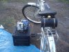
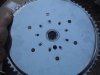
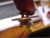
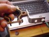
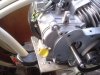
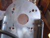
This build is just about done. I rode the bike for the first time yesterday and feel like I'm ready to share the ups and downs of this experience. In the end I'm happy with the results, but this was no easy build for me. The greyhound engine presented some real problems to solve and there were some wrong turns along the way. This is a budget build. No Worksman drum front wheel for this one. Lots of used stuff, made stuff, free stuff from friends and the dump, rebuilt stuff, all on a budget. I wanted to especially share the preparation of the engine and the mounting of it in the frame, since my hope is that it will help others contemplating a similar budget build, saving them some of the headaches I experienced. I think the Schwinn cantilever frame is a good choice for the Greyhound engine which is long, wide and just plain big. Before going on I want to especially thank the brothers Jim and Chris Davis who pioneered the greyhound engine used as a bike motor. It may have been done before somewhere, but on this forum it was a first. Jim's Schwinn Corvette was so good looking I was inspired and knew it could be done. Also hat's off to Scotto who's Trek build spurred me on and gave me some ideas. All three of these guys rock and freely shared their experiences with me. If it weren't for them I'd still be staring at the bike, trying to figure out what to do next.

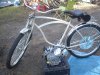
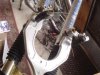
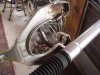
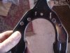
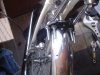
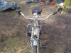
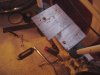
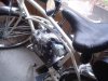
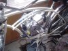
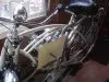
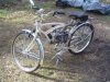
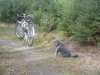
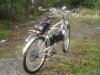
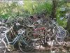
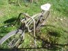
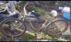
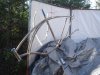
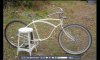
But let's begin with the bike. A month ago I shared some pictures from a vintage treasure hunt and among the finds was a 1951 Schwinn with a cantilever frame and springer front fork. It is somewhere down under that pile of bikes. It had a banana seat on it and had seen some rough use. From another bike in that same pile I found a cool seat and tried it out for looks along with setting a peanut tank on it. The tank would go as I have it in mind to make my first in frame copper tank this winter an until then will use a behind the seat tank which will eventually be an auxiliary tank to the copper one. I stripped the bike down to bare metal, primed it and gave it a coat of Wimbledon White in a Duplicolor rattle can. Finished it off with clear coat after waiting for the finish coat to cure enough. I liked it, but there was something very wrong with that front fork. With help from forum members it was determined that the front fork had been bent, probably by riding it without the struts. I ordered new struts for it along with a new spring and discovered that the struts were a good bit too long because the forks were bent that much. I have one strut sitting there in the photo, but not attached.
(cont)
 

Attachments

silverbear

The Boy Who Never Grew Up
Jul 9, 2009
8,325
670
113
northeastern Minnesota
http://motorbicycling.com/f38/schwinn-springer-help-needed-24416.html
The link is to the help thread I got from board members regarding the springer fork. I ended up making a compromise. I bent the the forks back most of the way to what they should have been, but was concerned about kinking or collapsing the forks, so didn't try to go all the way. This meant the struts were still too short so I lengthened the mounting holes at the axle end and made them into slots. The two approaches together made the front fork usable once more. The parts and shipping for repairing the front fork came to around $25.00 if I remember correctly.

http://motorbicycling.com/f38/rebuilding-vintage-seat-24473.html
This a thread showing how to rebuild a vintage seat, the one I used on this build. If you have an old seat with no upholstery or in need of fixing, this little tutorial should help you out. Vintage seats are not cheap to buy or have recovered if you can find someone to do it, but if you do your own you can have a great seat at little cost. I have a few dollars invested in this one. It isn't all that hard to do.

So with the addition of the 'new' seat, the front fork repaired and fresh paint the bike was coming together. For the rear rack I used a front rack from a mid sixties bike. These were popular in that time and came on many of the Schwinns as an option. This one came from a girl's monark which was given to me. The front mount originally fit on the front fork head tube. In this use I put a washer over the seat mounting post large enough to fit over the small end at the top and small enough to be stopped where the seat post widens. Te front mounting hole of the rack slips over the post and is stopped by the washer. The seat comes down on top of it so the front mounting point is secure. The rack legs attach to two small mounting holes at the upper rear corner of the dropouts. This is a very sturdy rack, good looking and was free. On it I mounted a behind the seat gas tank I made from a V8 juice can. How I make mine is in the archives of this forum and is shown in detailed tutorial.
The large chrome driven sprocket for the engine came from the dump and was came from an old Schwinn exercise bike. It is very heavy and well made, has 65 teeth and was right in the gear range of what I was looking for to go with the Greyhound engine. I wanted something capable of climbing hills without any pedaling. I had to drill new mounting holes to use with a 2 stroke kit rag joint. I laid the kit sprocket on top, centered, and with a marking pen laid out where to drill new holes. I used a punch to mark the spots, drilled pilot holes first and then with a bigger bit slotted them a bit for adjustment. While mounting on the wheel I had the bike upside down and spin checked for it being true and centered as I tightened down the bolts and hardware sandwiching the spokes. The sprocket was mounted dished side to the outside for chain clearance from the tire and also because the Greyhound is a wide motor. The rear wheel is coaster brake, heavy duty, and was ordered from bikeworldusa. It is a stout wheel with 12G spokes on the economy end of the scale. The chrome is not the best, but I have used these wheels before. For the money they fit with a budget build. I already had the front wheel and will detail how I made a front cantilever brake to it, coming up. Fenders are Wald from bikeworldusa.
Cont.
 

Attachments

silverbear

The Boy Who Never Grew Up
Jul 9, 2009
8,325
670
113
northeastern Minnesota
MAKING THE FRONT CANTILEVER BRAKE
I had a problem. No way to mount a front caliper brake on this fork. In 1951 no allowance was made on the springer fork for mounting one. With the reproductions I am told there is such a mounting hole. A plain caliper brake is minimal, but I think you must have something in a front brake in case the rear brake fails. I got the following idea from seeing a rear brake Scotto did on one of his recent builds... the Black & Blue thread, I believe, where he used a horseshoe shaped mounting plate he ordered on line for around $25.00 minus shipping. With it you can attach the hardware for a V pull cantilever brake, much superior in stopping power to the older caliper brake. That plate rang a bell and I rummaged through my pile of donor bikes scavenged from the dump. There it was; a 24" cheap mountain bike with a front fork having a plate very similar welded to it. I removed the fork and using a dremel cutoff wheel removed the plate from it. I set it in place trying to figure how I could mount it. All I could come up with was what you see in the last pictures. I drilled two holes on each side for a U bolt to fit through holding it fast to the springer fork struts. A little further down on the plate I attached stainless steel clamps. Then I hooked up the cable, attached it to a new brake lever with a build in electrical switch (for my brake lights), cut off the excess on the bolts and I had a front brake! I had no idea if it would hold up or not, but by the time the last photo was taken I had ridden the bike for several miles and can report that my freebie front brake rocks! I ordered new brake pads for it, Kool Stop salmon, for nine bucks. They are supposed to be the best. From what I have read on this forum, properly adjusted cantilever brakes are as good as a front hub brake. I won't enter into that debate, but they are good enough. So I have around $13.00 invested in the front brake (new pads, two U bolts and two clamps). I'm not counting the brake lever as that was ordered to activate the brake lights and would have been purchased anyway. The lever was about $7.00 with shipping... incredible buy from ebay. Look up electric scooter brake lever if you want one. So that last photo gives an idea of what the bike is looking like toward the end of the build after all the power unit stuff. I used the stock kit throttle after removing the housing and replacing it with a foam grip covered in hand stitched elk hide... the most comfortable grip I have ever used. They now go on all my bikes as they are kind to tired old hands. So the bike is now ready for the power plant which will be the next series of posts. Forget you saw that last picture with the engine in place, pretend it isn't on yet and we have to figure out how to mount it once we get the motor ready to power a bike. Now it gets interesting.
(cont.)
 

Attachments

silverbear

The Boy Who Never Grew Up
Jul 9, 2009
8,325
670
113
northeastern Minnesota
http://motorbicycling.com/f37/silverbears-greyhound-motor-mounts-24735.html
The above thread shows how I made inexpensive mounts for the HF motor. I don't know of any made specifically for the HF and they can cost as much as $50.00. Mine came to around $12.00.
So now we have a mount and are ready to do something with the motor. Like many of you with the Greyhound, I watched for their sale when the motor was listed at something like $95.00 for the normal $130.00, plus I had printed out a 20% off couplon for any one item in the store and that brought the cost down to less than $81.00 including tax. Pretty amazing. When my friend picked mine up for me at Harbor Freight and handed it to me he said, "kinda big, isn't it?". Oh, it'll fit, I said, remembering Jim Davis' Corvette, but wonderiang how the heck he got hthis monster in that frame. I opened up the box and dang that thing is big. Removing the gas tank and muffler shrunk it up a good bit and I figured I had to do something about that plastic air cleaner, so I made one.

http://motorbicycling.com/f37/flying-dogfish-air-cleaner-24718.html
(cont.)
 

Attachments

silverbear

The Boy Who Never Grew Up
Jul 9, 2009
8,325
670
113
northeastern Minnesota
It's a nice looking motor, nicely finished off compared to a China girl and with what seems to me a better pull start than the HS engine. I like the way the cyclinder kind of lays back in a reclining position which somehow seems right for a low revving, 'don't make me sweat' engine. I was impressed. Next up was to remove the governor mechanism which is pretty obvious on what to remove. I took pictures in the evening without flash and they are not worth posting. Sorry about that. Just remove the externals and save everything you remove. I reused some of it in making my throttle control.

http://motorbicycling.com/f37/greyhound-governor-throttle-help-needed-24752.html

This will give you some options and thoughts from others regarding both the governor and the throttle setup. In the photos below you can see Scotto's nifty carburetor swivel which has to be the best setup. I was too cheap to go that route and made mine from found stuff. You can see the washer (from the governor) with a hole drilled near the center and which has been slotted to the center so that the throttle cable can fit in there. With the little bolt in place the throttle cable can't go anywhere. The small bolt is from a caliper brake and the former governor arm (piece of bent wire) was cut off and fits right in that hole at the end of the bolt where it once allowed a brake cable to pass through. So that's the union point for the throttle cable and the little arm coming from the carburetor. Not as elegant as the store bought, but the price is right and it works very nicely. The last photo shows what I used to attach an anchor point for the throttle cable. It is something I had on hand and is a ground rod clamp used in electrical wiring for a home. I fit it around the seat post and attached a little corner brace to it which I also had in my 'trove of stuff that might come in handy some day' and fixed to it is another piece robbed from the same caliper brake donor that gave the little bolt used in the other photos. It is the housing piece for brake cable to fit through. I had to drill it out a little for the throttle cable, because remember it still has the molded stop on the end of the cable. So I made the hole big enough for the stop to fit through but small enough for the cable housing to be kept in place. What matters here isn't what hardware I came up with to use. It is the principles involved. Look around at your stuff or take a stroll through the hardware and some things will come to you. Fun stuff to fabricate out of junk.
(cont.)
 

Attachments

silverbear

The Boy Who Never Grew Up
Jul 9, 2009
8,325
670
113
northeastern Minnesota
Hey Elmo,
I managed to get 25 or 30 miles on it last week with some balmy weather just before winter ground things to a halt with six inches of snow and cold down to 16 degrees. So far it isn't melting. Yesterday I fired it up and cautiously rode it through the six inches out to the road which was plowed, but still wet with slush and dangerous spots. I went very carefully a mile or so to a spot where I could take some pictures with a lake as background instead of snow. A white bike in snow doesn't photograph well. The bike is all done now except for final wiring of the lights. I still have to figure out a way to power LED running lights off the engine and so far don't have a clue. Those pictures I took will come at the end of this thread. Up next is mounting the engine in the frame which was a headache, but worth it. I have a 65T driven sprocket in back and an adjustable pulley in the transmission. As it is, not yet broken in, the bike has good start from a dead stop power, smooth acceleration and walks right up hills. Just what I wanted! I'm happy with it. I'll be taking that bike with me to Maryland in early December so should have more opportunity to ride it there over the next several months. Hope so.
SB
 

Elmo

New Member
Sep 3, 2009
748
4
0
Mississippi
I have been thinking about a alt/gen off a riding lawnmower or other electric start yard equipment. There should be a way to hook it to my HF engine driven by a belt. Don't have one yet to figure out mounting and such like. Maybe a good winter project.
 

silverbear

The Boy Who Never Grew Up
Jul 9, 2009
8,325
670
113
northeastern Minnesota
Elmo, I keep thinking that since the engine produces enough electricity to give spark to the engine it has a magneto of some sort, probably pretty minimal like on the 2 stroke China girls... but enough to light up some low draw LED lights. I have to try it. Since the white wire on the HT motors is to the kill switch and also powers the lights, maybe the wire going to the on off switch on the Greyhound is the one to try lights with. Nothing to lose, I guess, in trying it. Do you know if it is a six volt system? I wired my throttle kill switch in to the low oil sensor wire... where it had plugged in to before I unplugged it. Works fine. Seems like nobody has tried running lights off the engine wiring yet. Guess I'll do some experimenting. If you play with it first, let me know.
SB
 

Fossil

New Member
Mar 15, 2008
228
2
0
Guthriesville Pa
Very nice write up silverbear. You left out one fun part. How to get the height of the engine mount high enough but not too high and far enough to the right but not too far to allow proper chain alignment and pedal clearance. Oh the fun!
Very informative silverbear and a very sharp looking build too!

Jim
 

silverbear

The Boy Who Never Grew Up
Jul 9, 2009
8,325
670
113
northeastern Minnesota
Thanks, Jim. I still have more to do on this thread and will try to get to the part you mentioned over the weekend, then explain the really fun part of mating the transmission to the engine. Now that I know how it isn't so perplexing. It's like a math problem, once you know how then it's easy. Well, pretty easy. But you need to have a method or a formula to work with and between us and your brother, Scotto and those yet to come, we're working out the methods and a formula. I hear your brother is starting a new Greyhound build in a vintage Shelby... awesome! Wish I could be riding, but it is five degrees here and blowing snow. Should be in Maryland in a couple more weeks and on a nice weekend want to come up to PA to see you guys & check out your bikes.
SB
 

silverbear

The Boy Who Never Grew Up
Jul 9, 2009
8,325
670
113
northeastern Minnesota
Back to the mounting of the engine into the frame of the bike. I looked back over old posts and found this in the section on making the mounting plate. It tells how to locate the plate ON THIS PARTICULAR FRAME. A different kind of frame and none of this applies other than by chance. But if you have an old Schwinn with the cantilever frame the following information should do you good.

"I emailed Jim Davis last evening to see how high or low his mounting plate was. It seemed to me that I had mine too low since when I sat the motor in place the pedal was running in to it in spite of the extra wide crank. Jim used the same motor with the same frame design, also a Schwinn cantilever. He measured his from the underside of the lower bar along the seat post to the back edge of the mounting plate and came up with 8 1/2". Mine was 2 " lower( or 10 1/2"). Jim suggested a compromise since he has difficulty changing his spark plug and wishes now that his was a bit lower. So that is what I did today, drilling new holes in the mounting plate so that the angle iron underneath could move out to each end of the plate. The measurement for mine is 9 1/2 inches... this is measuring "from the underside of the of the lower cross bar along the seat post to the back edge of the mounting plate". Much higher and you have clearance issues with the spark plug. Lower you run into the pedal. Goldilocks would say this one is jes right for this cantilever frame, which I think is a perfect candidate for the Greyhound. The plate itself measures 6" X 9". An inch longer would be better. "

I also ended up notching out the rear section of the left hand side of the plate once I had the transmission lined up. The first photo shows what I cut out.
I have been putting off writing this section of the install, trying to figure how to make it simple when at the time I was very much perplexed on what to do and how to proceed.
I asked Jim how he aligned the engine from side to side in the frame. On his build he had the drain plug (at the front of the engine on the Greyhound approximately 5/8" to the right of the front down post. Skotto reported that his was centered so that the drain plug and the front down tube were aligned. I ended up bolting mine down in a compromise of the two, just to the right of center about a quarter inch. The differences may have to do with how each of us set up our driven sprocket. If you were to elongate your bolt holes in the plate so that the motor could be adjusted a bit from side to side that would be ideal. Now, how to locate where to drill the holes in the plate for mounting your motor?
Once I had the engine in place in relation to the front down tube I lined it up front to back. The engine is so long that there wasn't much choice. You don't want it up against the seat post at the back and that pretty well puts it as far forward on the plate as it can go. So the engine is sitting there. Using a marking pen I outlined the bottom of the engine on the plate. With the engine removed I could see where it had been from the outline remaining on the plate. Now I made a template of the bottom of the engine. I used stiff cardboard from a file folder, set the engine on it and traced the base of the engine onto the cardboard in much the same way I had on the mounting plate. Then I cut out the tracing with scissors. I taped the edges enough to hold the cut out piece against the base of the engine. Then I used the wooden handle end of an awl (screwdriver would work) and rubbed it against the bottom of the engine all over. This left impressions in the cardboard of exactly where the bolt holes are on the engine. I removed the cardboard from the engine, placed it back on the mounting plate into the outline from before, taped it enough not to move and using a nail set (couldn't find my metal punch) and a hammer I made a dink in the plate at each of the four bolt hole locations. Then I remove the cardboard and drilled the holes. I hope this is clear enough to understand. A lot of fussing, but now you have the engine mounted. True confessions... I had to open up a couple of the holes I had drilled, making them larger in order to get the motor positioned right. Looking from underneath it isn't pretty and looks like somebody didn't know what they were doing. Correct. I used large enough fender washers from the hardware store along with lock washers to secure the bolts to the engine. if you do a better job than me of drilling the holes you won't need fender washers. The next part took me a couple days of staring, postponing, more staring to finally figure out... mounting the transmission the engine. How would you do it?
(cont.)
 

Attachments

silverbear

The Boy Who Never Grew Up
Jul 9, 2009
8,325
670
113
northeastern Minnesota
I forgot to explain what the picture with two hammers is about. I put a clamp under each of the motor mounts to insure they can not go anywhere under torque from the engine. I use old seat post clamps and never throw away the old steel ones from dump bikes. They're useful! To use them here you have to open them up enough that they'll fit around the frame. After much trial an error this is how I do it using two claw hammers. Pretty low tech, but it works. Once you have it in place use an extra long bolt and nut to draw it back in, bending the clamp back to the way it was. Once it has been re-bent you can use your original nut and bolt.
This thread is not done. Don't change your radio dial to another station! We are at a cliff hanger here... how to figure out where to drill holes in the transmission backing plate to attach it to the motor? Remember, it has engine holes in it, but they are for the HS engine and are entirely different. This is your assignment if you choose to accept it. How would you do it?
(Cont.)
 

bjpru66

New Member
Mar 9, 2008
32
0
0
Arizona
Your build looks really good to this point.
I think I would make an adapter plate out of 1/8" mild-stainless steel
and put studs on it where needed to mount the trans. mounting plate,
so you could just use nuts, washers, ect. to mount the trans. to it.
Just my 2 cents worth.
Love the paint color choice.
 

cannonball2

Well-Known Member
Oct 28, 2010
3,682
221
63
Colonial Coast USA.
If you havent found an alternator yet, here are a few pics of a Briggs unit off an electric start Intek. The beauty is this one mounts externally to the flywheel and is energized by the same magnets used for the ignition. It was used to charge the battery for the electric start. It is unregulated so I doubt its output will exceed 14+V DC. Would just have to figure out a mount.
 

Attachments

silverbear

The Boy Who Never Grew Up
Jul 9, 2009
8,325
670
113
northeastern Minnesota
I'll try to do the next installment of the build thread this evening, but I wanted to thank Bill for the nice comment and Cannonball for the tip on the alternator. That thing looks promising! i did some looking on ebay and found nothing. I wonder what one of those units costs and what they are rated at in wattage. I wonder if it would fit on the Greyhound or HS So this must not fit on the flywheel itself or does it somehow? It must be stationary or the wire would get ripped off I would think. If a flywheel is plastic would it still work? It's obvious from my questions that I do not understand how this mounts, but if there is a way, this would be way cool. Or something like it from some other kind of engine.
SB
 

cannonball2

Well-Known Member
Oct 28, 2010
3,682
221
63
Colonial Coast USA.
This mounts exactly like an ignition unit to the engine block. As the magnets spin by power is generated. I am not exactly familar with the engine you have, but if its a Honda clone or close there should be some way to mount this unit. One way may be a simple bracket mounted to the same bolts holding the ignition unit. As stated this was meant to charge a small 12v battery used to start the mower with. As it is unregulated is was probably designed with an output of maybe .5 to 1amp and 14vdc to keep from overcharging the battery. Plenty for lights. The unit doesnt care about the material of the flywheel as long as there are external ignition magnets to generate the charge. There should be 2-3 depending on design. I am sorry I dont have the part# but I can look it up on line if you need it. I retired from the small engine business in 08. At that time these cost in the low $20. Dont have a clue now.
 

silverbear

The Boy Who Never Grew Up
Jul 9, 2009
8,325
670
113
northeastern Minnesota
cannonball2,
This looks very promising. If you wanted to wholesale these I'm sure there would be plenty of customers here to help you make a profit. I want to follow up on this...
SB
 

silverbear

The Boy Who Never Grew Up
Jul 9, 2009
8,325
670
113
northeastern Minnesota
I've been negligent about continuing this build thread. so here's the next installment. We were at a point of needing to marry the Qmatic transmission to the engine. I spent a couple of days thinking and staring and coming up blank on how to proceed. The transmission already has mounting holes drilled in it, but it is for a different motor. Once you press the transmission plate up against the engine, you can no longer see the engine mounting holes. It is essential that the crankshaft be centered in the large hole in the transmission mounting plate. That's where the pulley is going to go.
Here's what I finally did... You probably would have figured this out long before I did, but no matter so long as we figure out a way.
First photo shows a file folder with a cut out for the engine shaft. Ihave the ofolder resting against the engine mount.
Second photo I am making a rubbing. I put a little bit of axle grease on the raised surfaces of the engine, at the edges, at the mounting holes and pressed the file folder against the motor. I used the wooden handle of a leather awl, but a screwdriver handle or wooden spoon... something will work to press the cardboard against the engine and make an accurate impression.
Third photo shows the results. Now we have an accurate template of the engine. I cut out the outline of the engine on the template and then put it back against the engine and taped it in place as shown in the fourth picture.
Next I placed the transmission against the engine and found the best position where the crankshaft was centered in the transmission backing plate. Once I was happy with the position of the tranny I used a marking pen to mark through the bolt holes in the transmission and also marked along the edge of the file folder where I could . These are for reference points... what had been hanging me up for a couple of days. I couldn't figure out how to have accurate reference points until I saw this in my head. The proverbial light bulb got brighter and I could see this would work. So the last photo shows the template still against the engine with the new reference points. With this key we can unlock the problem of where to drill new mounting holes in the transmission...
(cont.)
 

Attachments

silverbear

The Boy Who Never Grew Up
Jul 9, 2009
8,325
670
113
northeastern Minnesota
The first picture below shows the template lined up and taped to the transmission mounting plate. It is aligned so that the marked edges and the marked bolt holes line up with the transmission and the template is taped down using all the reference points. Now we can see very clearly exactly where the Greyhound mounting holes need to be drilled in the transmission plate. I marked the spots with a metal punch, drilled the holes and the plate (second photo) is now ready to join the engine in mechanical matrimony. The holes with arrows are the new ones for the Greyhound.
Not shown is the new location of the idler pulley, moved a inch or so to not conflict with the engine block. This same procedure in making a kind of double or two sided template would work for any match up of this transmission with a different engine. So long as the crankshaft is centered and you can bolt the two together you're good to go. This was for me the single hardest thing to figure out on this build and what took the longest. Next time I'll know just want to do and can zip right along. Now you know, too. Last couple photos show the bride and groom together at last and looking good. That's enough for tonight. To be continued... but not a whole lot left.
SB
 

Attachments