3 speed Elgin Velocipede 1934

GoldenMotor.com

silverbear

The Boy Who Never Grew Up
Jul 9, 2009
8,325
670
113
northeastern Minnesota
Thanks, Steve. At least we'll have an area to work this summer, out of the way. When your shop is outside there's plenty of room. It works. We have a dedicated 110 V. line for the welder, a place out of the weather inside the bike trailer to keep the welder dry. I clamp a 52 Schwinn frame in the vice for truing wheels. A couple of picnic table benches along the wall of the trailer I live in has tool boxes covered in tarps for easy access to wrenching tools and the side grinder. It works OK so long as it isn't raining and you have bug repellent when needed. Beats no place to work by a long shot. We manage to do some good stuff in spite of, don't we? A real garage would sure be nice. I could live in one and sleep on a cot... get up in the morning and get right to a build and on a rainy day keep right at it. Maybe someday when I grow up.

Your velocar will be enclosed with a roof? And a skylight? If I ever get to it, mine will be a roadster, but a folding buggy type top would be nice when it rains. We'd better live to be a hundred or we'll never get all these projects done. Speaking of which, I've got work to do... later.
SB
 

fasteddy

Well-Known Member
Feb 13, 2009
7,445
4,888
113
British Columbia Canada
Could say that your shop is as big as all outdoors. :)

You have to remember that if you live in the North West you don't tan, you rust so a roof is a must if you plan to use it year around.
The other option is Arizona in the winter when we get our rain season.

We have created some nice bikes between us while in the birches and pines.

Fast(old rusty)eddy
 

silverbear

The Boy Who Never Grew Up
Jul 9, 2009
8,325
670
113
northeastern Minnesota
In between work on sealing up the Panther gas tank, fishing and riding bike I've gotten some progress made on the Elgin.

I removed all of the sub structure on the buggy so that now it sits directly on the sidecar frame which is much better. Not shown is the work I did this evening dismantling the sidecar itself. It is now in it's separate pieces to be stripped, repaired and repainted. The chrome is actually pretty bad, so I may end up painting the chrome either gray or silver. Will think on it some.

I've also taken the canopy apart stitch by stitch, taking pictures as I went and figuring out how it will go back together again. The Naugahyde should be here tomorrow or Monday.

Parts arrived yesterday from SBP for the shift assembly... pedal arms and the bottom bracket axle. II bought the widest one they have (three choices) since I have a pull start on the HT engine and am anticipating a different and wider engine sometime in the future... hopefully a Villiars 98cc midget. Over the next few days I'll be studying the recommendations of Ghosto and Pablo at SBP in the PDF how to files. What I'm doing will be somewhat different since my jackshaft will fit directly on the seat tube and not on the engine itself. I'm also not using their engine mounting system, so some head scratching and creative stares are in order.

I'm also going to ask Cannonball2 for some advice since he is the one who made the jackshaft and had it mounted on his bike. If anybody knows the ins and outs of this particular setup it is him. So, CB2 if you're reading this by chance please advise as you will. I could use your input right about now.
I thought about asking my questions privately by PM, but thought if we do it here on this thread then others might benefit from your experience and have the opportunity to comment or ask questions. If you would be so kind, sir.

And that's about it for now.
SB
 

Attachments

cannonball2

Well-Known Member
Oct 28, 2010
3,682
221
63
Colonial Coast USA.
Well SB, my thoughts on the seat tube jackshafts have evolved a bit since the shifter bike. For a build with an industrial engine like a Preddy, I now prefer the jackshaft mounted to the engine mount, in my case simple angle iron. Generally I pivot it at the bottom for adjustment. Most of my builds are belt primary, which I think is the way to go if possible. The adjustment/lash issues with two chains is not to my liking. My current Lifan 125 is a double chain and it took some careful tweeking to get the lash out. My current Lifan 70cc build has been converted to a belt primary for this reason. This is not so much an issue on a bike that isnt shifted, but can make a shifted bike an unpleasnt ride if not delt with.

My lastest jackshaft mounting method I am sure you have seen it, uses 1 1/8" bearing lock collars. This has proven a killer method in my last three builds. They are also the engine mounts for my Lifan bikes. I believe the jackshaft you have can be used with these, as is. May take a new shaft to widen it a bit for the collars. The beauty is full adjustability if needed and easy removal of the entire assembly if necessay. If adjusted by another method then the top collar rear half can be basically tack welded in place to hold the drive indexing. I can post links if you like.
 

silverbear

The Boy Who Never Grew Up
Jul 9, 2009
8,325
670
113
northeastern Minnesota
Cannonball2,
Thanks for checking in and helping out. Having already invested a good bit of time, money and effort in this build, I want to do it right and have the results be a satisfying reward. I've read about the lash issues and wish to make the shift assembly as trouble free as I can.

Yes, if you would post the links, that would be good. I will study your Lifan bikes in regard to the 1 1/8" lock collars. Can you also give me the link to your original build which used this jackshaft I now have? The more I can stare at photos the better things sink in to me little brain. Then I know better what to ask. Thank you, sir.
SB
 

cannonball2

Well-Known Member
Oct 28, 2010
3,682
221
63
Colonial Coast USA.
Heres a link to the shifter build with the pics you wanna see, and some new pics of the(strangely enough the same bike) current Lifan 70s jackshaft. You can also see the collars used to mount the engine. I have yet to have these collars shift, even with the attempts to pedal start the 1900s Vintage bike which really loaded them! Im thinking just weld the jackshaft you now have to a set of collars if you want to use this method. If you look closely you can see the welded holes in the seat tube where your jackshaft was mounted. The beauty of the collars is down the road if you want to do something different, they unbolt leaving the bike in its original condition. BTW I always drive a thick walled seat post down to the bottom bracket to strengthen the seat tube.http://motorbicycling.com/showpost.php?p=297162&postcount=1
 

Attachments

silverbear

The Boy Who Never Grew Up
Jul 9, 2009
8,325
670
113
northeastern Minnesota
CB2,,
Yes, I can see that your current setup is superior. Not only does it not alter the original bike, but it is also adjustable... up, down and twisting side to side. Very nice. I think this is the way to go. Where did you purchase them?
SB
 

silverbear

The Boy Who Never Grew Up
Jul 9, 2009
8,325
670
113
northeastern Minnesota
Tinsmith sent me a set of handlebars I like much better than the shorties I had on it temporarily. We each bought a set of these as apehangers a year ago and cut off the "apes". I used mine on my Panther and once I got used to them, like them a lot. Dan didn't like his and went a different route, so that's how I've come by the handlebars. Thanks, Dan!

I wasted at least an hour today trying to find the dual pull brake levers I know I have, but am thinking I must have left them in Maryland. So, I'll make do with separate brake levers on each side until fall.

I also wanted to show the center support for the front fender which will allow the fender to ride up and down with the legs of the sprung fork. Holes will be drilled and attached with bolts. I made the support from an extra fender bracket and shortened it to suit, flattening it out some in the vice. It also bolts to the fender at the top.
SB
 

Attachments

silverbear

The Boy Who Never Grew Up
Jul 9, 2009
8,325
670
113
northeastern Minnesota
I found the dual brave lever so that's one step forward. And I've started stitching up the new Naugahyde canopy for the sidecar, so that's another baby step forward.

The split collars arrived and I had to go check them on the seat post for fit (had a nagging feeling I'd forgotten something) and discovered they are too big. Bummer. They are 1 1/8" and what I need are 1". It never dawned on me at the time to check the diameter. Ah well, maybe I can use them on something else. So that's a step backwards to be made right by ordering the right size.
SB
 

cannonball2

Well-Known Member
Oct 28, 2010
3,682
221
63
Colonial Coast USA.
Sorry SB, I should have thought when I provided the link to the 1 1/8s to say to check the diameter. Most of the newer bikes are the larger size. Kinda went right by me about your bike being older, even though the thread title has 1934 prominently in it. Maybe on the next build.
 

silverbear

The Boy Who Never Grew Up
Jul 9, 2009
8,325
670
113
northeastern Minnesota
CB2, That's my oversight, not yours. I thought about asking them to exchange them, which I'm sure they would have done, but after postage there and back that makes little economic sense. There will be a use for them either by me or someone else. Not a big deal.
SB
 

silverbear

The Boy Who Never Grew Up
Jul 9, 2009
8,325
670
113
northeastern Minnesota
It has been awhile. Now that my 50 Panther is back together I can give some time to the 34 Elgin. I ordered the correct size split collars (1") for holding the jack shaft to the seat post and they have arrived. I also ordered pedal adapters so that I can use vintage 1/2" thread pedals with 9/16" sockets on the pedal arms and they also arrived.

Today I mounted the bottom bracket adapter so that what was a one piece crank can now become a three piece which is needed to utilize the SBP freewheel. The cartridge with axle is also installed, but I have a question. If you look at the closeup photo you can see a good bit of threading showing on a fitting which threads into the bracket adapter. It seems to me it should go in further, but without what I imagine must be a special tool for that purpose I don't know how to thread it in any further. Is there a tool for this? What is it called?

I ordered the longest axle SBP sells ( three options) in order to give as much engine clearance as possible. I knew I would be using a pull start China Girl initially and wanted to clear the extra width of the case at the pull start. But I also wanted to anticipate a change in engines in the not too distant future. Thanks to Fasteddy (Steve) he has decided to not use his villiars 98CC midget and is passing the engine along to me for the Elgin. He agrees that it should look just right. As I write he is on his way from British Columbia for a month or so of motor bicycle camp at my place on Eagles Nest Lake in northeastern Minnesota. The vintage Villiars is packed away in his camper trailer along with his very cool electric 1950's Monark Silver King deluxe with Chris Craft inspired mahogany decked sidecar. Beautiful!

The bike will start out with the PK-80 engine to work out the bugs and get the shift kit part of the build squared away. We'll weld up engine mounts for the Villiars this summer but I won't change the engine over until winter. I'm hoping there will be a way to utilize the Villiars kick start mechanism. We'll see.

I'm also in the process of putting the buggy sidecar back together. It has been repaired and painted. I still have the canopy to stitch up. Pictures of that will follow when I'm a little further along.

One of the photos shows the right side of the bike with the freewheel and sprockets sitting on the axle... just so that I can see that the sprocket is not too big for the original chain guard which I want to use. Actually not that one, but another one I have just like it (but in poor condition) which was damaged in a fire. It will need to get butchered a bit so the chain from the jack shaft can link up with the driven sprocket next to the pedal sprocket. I need to use the chain guard not just for aesthetics, but also because it is what the right side fender skirt attaches to. No chain guard then no fender skirt and that isn't gonna happen.
SB
 

silverbear

The Boy Who Never Grew Up
Jul 9, 2009
8,325
670
113
northeastern Minnesota
Yes, it does, Norm. I just did some wandering around on the SBP site and found the tool I need. Just ordered it five minutes ago. Their shipping is always quick so I should have it in a few days
SB
 

silverbear

The Boy Who Never Grew Up
Jul 9, 2009
8,325
670
113
northeastern Minnesota
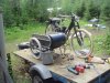
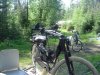
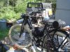
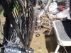
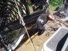
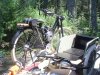
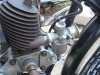
Well, I've decided to change horses mid stream, so to speak. First photo shows the bike with the PK-80 engine. I'm sure this engine with the expansion pipe and three speed transmission would have made a nice combination. But for this old bike it just doesn't look right, to my eye, and the sound will also be "off" for a 1934 motor bicycle. Even though the change I'm making will set the completion of the bike farther into the future, in the end I think it will be worth the trouble.
So, the PK-80 with pipe will get listed under swap and shop tomorrow.

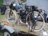
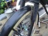
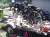
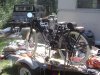
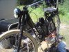
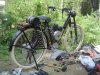
The "new" engine is a 1940's British made Villiars 98cc 2 stroke. It is heavy, durable and slow revving. Even with higher displacement, it may not outperform the PK-80. I don't mind if that's the case because to my eye this engine looks right and having heard them on U tube I know it will sound right, too. Especially with the sidecar, I'm not interested in going very fast. I think 30 mph as a cruising speed is the upper limit for this old timer.

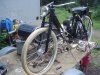
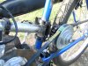
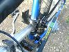
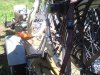
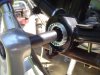
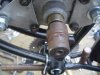
So that's what's up. Since these photos were taken this morning I have made a new rear engine mount which allows me to lower the engine more. The engine mounts will be welded to 1" split collars so there will be no welding or alteration of the frame. The collars are going to work very well I think and will allow me to adjust the fit of the engine.

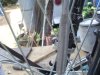
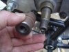
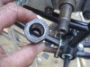
The jackshaft I got from Cannonball2 looks like it will be a problem mounted behind the seat post, so after some long staring this evening Fasteddy and I came up with a different location which is forward of the engine and will attach to the front down tube by means of another set of 1" split collars. At least that's what we're thinking at this stage. I have ordered a second set of collars since two will be needed for the engine mounting and two for the jackshaft. The collars will allow for no drilling or welding of the frame and will also be adjustable. I like these split collars a lot.

I think what we're going to do is use a Max Torque clutch with bearings instead of bronze bushings and a pulley belt drive for the primary drive to the jackshaft. Then chain drive from the jackshaft to the freewheel. My understanding is that this makes for a smoother drive line.

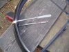
I wanted to use the kick start with this engine, but there is no way to make it work on a bike. This engine was originally used on a lawnmower and the kick start is all wrong for fitting onto a bike. My leg would be running into the kick start, so it is out which leaves just a couple of options for starting. I could use a setup similar to what Harry 76 did with his Villiars Beach Cruiser (one of my favorite builds) which used a lever and idler to engage the belt drive. If I did that then theoretically I could start the engine with the pedal as a kind of kick start. One problem with that is fitting up the lever which requires a good bit of reach and leverage. With no upper cross bar that limits where to anchor the lever. The other option is an automatic clutch which would not allow the pedal start, I believe. About the only way to start it would be with a leather belt wrapped around the flywheel... which is the way I'm going to go. The inconvenience of a belt pull start will be offset by the convenience of the automatic clutch (no need to disengage the belt when coming to a stop). More tomorrow...
SB
 

Attachments

harry76

Well-Known Member
Apr 16, 2011
2,557
47
48
Brisbane, Australia
Hey Silverbear, good to see that Villiers engine again. I really like this bike and agree with you about the older motor suiting this build more.

Im not sure if you realise, but to my knowledge there is no off the shelf centrifugal clutch that will work with that motor, but supposedly you can change the springs to suit, or possibly Comet make them per order for certain specs. If i remember correctly these engines only rev to 1600rpm and thats when most clutches activate.

Another option is doing a similar pulley tensioner like i have on my bike, but cable activated rather then by a handle. So the tensioner would be held against the belt by a spring, and have a cable attatched and when the cable is pulled in it releases tension on the primary belt. Hope that makes sense. I plan to use this setup on my next Villiers build.

I actually just bought another Villiers/Atco mower for $20, yet to pick it up.

http://www.ebay.com.au/itm/261060708013?ssPageName=STRK:MEWNX:IT&_trksid=p3984.m1497.l2649
 

silverbear

The Boy Who Never Grew Up
Jul 9, 2009
8,325
670
113
northeastern Minnesota
I'm glad to see your post, Harry, and appreciate your input. I was going to PM you about the Villiar's RPMs, but now I know. I knew it was a kind of put put motor something like a Maytag. I had contacted the Max Torque people and they will set up the springs the way a customer wants them, but considering how slowly this engine turns over I think a centrifugal clutch may not be the best option.

I very much like your concept of a cable or lever moving the idler pulley out of tension rather than the other way around. It should take a lot less leverage. Going that route will keep things simple and also save me a hundred bucks or so, which is always a consideration. Steve and I have been considering everything from a locking clutch lever with cable, to a foot operated lever from one of several moped/dirtbike donors to a lever with ball on the end. All I really need to know at this point is the concept and that there will be no automatic clutch. So thanks again for your valuable input. Any other suggestions from anyone will be appreciated and considered.

I made a little progress today in removing the pedal chain guard so the freewheel can go in place. I also painted the pedal arms to make them jump out a little less. They are obviously modern and there's little way to get around that. But being black like the frame your eye doesn't tend to zero in on them, so that's the best I can do. I also removed the kick start gear hardware from the end of the flywheel so it won't catch on clothing

The last three photos show the engine crankshaft where a pulley will need to go. As it is there is a tapered shaft with a fitting on the end which is stepped in diameter. The outer portion appears to be 1" in diameter. This threads onto the tapered shaft and has Whitworth threads. My thought is to have this turned down to 3/4" and have a key way cut into it to match that of the pulley.
SB
 

Attachments